
Page 194 - Intelligent Digital Oil And Gas Fields
P. 194
150 Intelligent Digital Oil and Gas Fields
5.1 INTRODUCTION TO PROCESS CONTROL
Process control is an engineering mechanism that uses continuous
monitoring of an industrial process’ operational variables (e.g., temperature,
pressure, chemical content) and algorithms and then uses that information to
adjust variables to reach product output specifications and objectives. Pro-
cess control can be a partially or fully automated system capable of
maintaining a consistent product output.
Any industrial process loop requires measurement, comparison of data
against set points, and continuous adjustments. Systems can be closed feed-
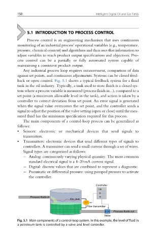
back or open control. Fig. 5.1 shows a typical feedback system for a fluid
tank in the oil industry. Typically, a tank used to store fluids is a closed sys-
tem where a process variable is measured (process fluids in...), compared to a
set point (a maximum allowable level in the tank), and action is taken by a
controller to correct deviation from set point. An error signal is generated
when the signal value overcomes the set point, and the controller sends a
signal to adjust the position of the valve setting (open or close) until the mea-
sured fluid has the minimum specification required for this process.
The main components of a control-loop process can be generalized as
follows:
• Sensors: electronic or mechanical devices that send signals to
transmitters.
• Transmitters: electronic devices that send different types of signals to
controllers. A transmitter can send a small current through a set of wires.
Signal types are categorized as follows:
Analog: continuously varying physical quantity. The most common
standard electrical signal is a 4–20mA current signal.
Digital: discrete values that are combined to represent a diagnostic.
Pneumatic or differential pressure: using pumped pressure to activate
the controller.
Controller
100
50
Process fluids in 10
Max level
FT
Flow transmitter
Process fluids out
Valve
Fig. 5.1 Main components of a control-loop system. In this example, the level of fluid in
a petroleum tank is controlled by a valve and level controller.