
Page 213 - Intelligent Digital Oil And Gas Fields
P. 213
Workflow Automation and Intelligent Control 167
valve sizes. VFM models are used and reconciled in three zones of operation
(beginning at the surface): the wellhead and choke, the well trajectory and
wellbore, and the near wellbore-reservoir area.
5.3.1 VFM Physical Models
Choke models. This is the first level of calculation for a VFM model. The
choke model is used to determine the flows through a choke or orifice under
both critical and subcritical flows. The model uses flow-dynamic equations
such as Gilbert (1954), Ros (1960), and Perkins (1993) models to predict and
back allocate the total liquid or gas. Eq. (5.1) is a generalized expression of
Gilbert correlation as follows:
1 a 1 THP GOR a 2
¼ a 3 (5.1)
Q L Surf d
64
where Q L-Surf is the total liquid rate at surface condition in STB/d; oil rate
can be calculated by multiplying the water cut (WC) ratio with total liquid;
THP the tubing head pressure in psi; GOR the gas-oil ratio in SCF/STB, d
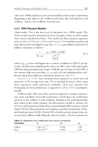
the current choke size over 64in.; a 1 , a 2 , and a 3 are the multiphase flow coef-
ficients taken from different correlations shown in Table 5.3.
Rastoin et al. (1997) have simulated these equations to match rate and
observed <13% average error and 17% in standard deviation, when using
these expressions under subcritical conditions. They have reported that
Perking has the best performance compared to Gilbert (1954) mechanistic
models.
Wellbore model. This zone of the system is required to estimate total pres-
sure drop and fluid vertical lift performance (VLP) from the perforation
intervals in the wellbore to the wellhead. Starting at the perforation holes
and ending at the choke position, the information needed to estimate the
VLP are: well trajectories [defined by measured depth (MD) and true vertical
depth (TVD)], tubing diameter and roughness, geothermal gradient, GOR,
and liquid-gas ration (LGR). Nearly 65% of total reservoir energy losses can
occur in the wellbore while lifting the oil to the surface. The best equation to
Table 5.3 Multiphase Flow Coefficients From Various Correlations
Correlation a 1 a 2 a 3
3
Gilbert 3.86 10 0.546 1.89
Ros 4.26 10 3 0.500 2.00