
Page 166 - Intro Predictive Maintenance
P. 166
Vibration Monitoring and Analysis 157
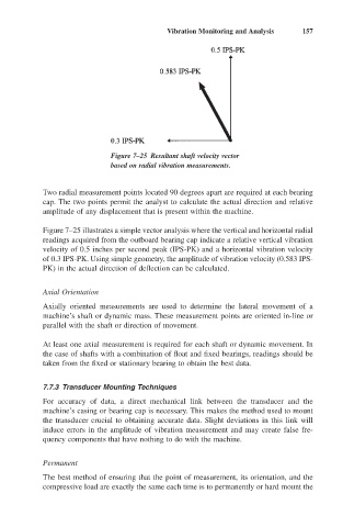
Figure 7–25 Resultant shaft velocity vector
based on radial vibration measurements.
Two radial measurement points located 90 degrees apart are required at each bearing
cap. The two points permit the analyst to calculate the actual direction and relative
amplitude of any displacement that is present within the machine.
Figure 7–25 illustrates a simple vector analysis where the vertical and horizontal radial
readings acquired from the outboard bearing cap indicate a relative vertical vibration
velocity of 0.5 inches per second peak (IPS-PK) and a horizontal vibration velocity
of 0.3 IPS-PK. Using simple geometry, the amplitude of vibration velocity (0.583 IPS-
PK) in the actual direction of deflection can be calculated.
Axial Orientation
Axially oriented measurements are used to determine the lateral movement of a
machine’s shaft or dynamic mass. These measurement points are oriented in-line or
parallel with the shaft or direction of movement.
At least one axial measurement is required for each shaft or dynamic movement. In
the case of shafts with a combination of float and fixed bearings, readings should be
taken from the fixed or stationary bearing to obtain the best data.
7.7.3 Transducer Mounting Techniques
For accuracy of data, a direct mechanical link between the transducer and the
machine’s casing or bearing cap is necessary. This makes the method used to mount
the transducer crucial to obtaining accurate data. Slight deviations in this link will
induce errors in the amplitude of vibration measurement and may create false fre-
quency components that have nothing to do with the machine.
Permanent
The best method of ensuring that the point of measurement, its orientation, and the
compressive load are exactly the same each time is to permanently or hard mount the