
Page 260 - Intro Predictive Maintenance
P. 260
Process Parameters 251
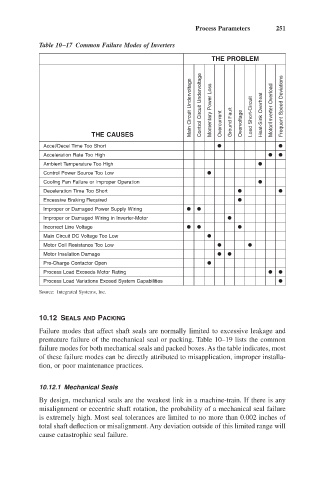
Table 10–17 Common Failure Modes of Inverters
THE PROBLEM
Main Circuit Undervoltage Control Circuit Undervoltage Momentary Power Loss Load Short-Circuit Heat-Sink Overheat Motor/Inverter Overload Frequent Speed Deviations
THE CAUSES Overcurrent Ground Fault Overvoltage
Accel/Decel Time Too Short
Acceleration Rate Too High
Ambient Temperature Too High
Control Power Source Too Low
Cooling Fan Failure or Improper Operation
Deceleration Time Too Short
Excessive Braking Required
Improper or Damaged Power Supply Wiring
Improper or Damaged Wiring in Inverter-Motor
Incorrect Line Voltage
Main Circuit DC Voltage Too Low
Motor Coil Resistance Too Low
Motor Insulation Damage
Pre-Charge Contactor Open
Process Load Exceeds Motor Rating
Process Load Variations Exceed System Capabilities
Source: Integrated Systems, Inc.
10.12 SEALS AND PACKING
Failure modes that affect shaft seals are normally limited to excessive leakage and
premature failure of the mechanical seal or packing. Table 10–19 lists the common
failure modes for both mechanical seals and packed boxes. As the table indicates, most
of these failure modes can be directly attributed to misapplication, improper installa-
tion, or poor maintenance practices.
10.12.1 Mechanical Seals
By design, mechanical seals are the weakest link in a machine-train. If there is any
misalignment or eccentric shaft rotation, the probability of a mechanical seal failure
is extremely high. Most seal tolerances are limited to no more than 0.002 inches of
total shaft deflection or misalignment. Any deviation outside of this limited range will
cause catastrophic seal failure.