
Page 255 - Intro to Tensor Calculus
P. 255
249
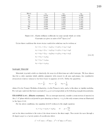
Metal c 11 c 12 c 44
Na 0.074 0.062 0.042
Pb 0.495 0.423 0.149
Cu 1.684 1.214 0.754
Ni 2.508 1.500 1.235
Cr 3.500 0.678 1.008
Mo 4.630 1.610 1.090
W 5.233 2.045 1.607
Figure 2.4-1. Elastic stiffness coefficients for some metals which are cubic.
Constants are given in units of 10 12 dynes/cm 2
Under these conditions the stress strain constitutive relations can be written as
σ 1 = σ 11 =(c 11 − c 12 )e 11 + c 12 (e 11 + e 22 + e 33 )
σ 2 = σ 22 =(c 11 − c 12 )e 22 + c 12 (e 11 + e 22 + e 33 )
σ 3 = σ 33 =(c 11 − c 12 )e 33 + c 12 (e 11 + e 22 + e 33 )
(2.4.18)
σ 4 = σ 12 = c 44 e 12
σ 5 = σ 13 = c 44 e 13
σ 6 = σ 23 = c 44 e 23 .
Isotropic Material
Materials (crystals) which are elastically the same in all directions are called isotropic. We have shown
that for a cubic material which exhibits symmetry with respect to all axes and planes, the constitutive
stress-strain relation reduces to the form found in equation (2.4.17). Define the quantities
1 ν 1
s 11 = , s 12 = − , s 44 =
E E 2µ
where E is the Young’s Modulus of elasticity, ν is the Poisson’s ratio, and µ is the shear or rigidity modulus.
For isotropic materials the three constants E, ν, µ are not independent as the following example demonstrates.
EXAMPLE 2.4-1. (Elastic constants) For an isotropic material, consider a cross section of material in
1
2
the x -x plane which is subjected to pure shearing so that σ 4 = σ 12 is the only nonzero stress as illustrated
in the figure 2.4-2.
For the above conditions, the equation (2.4.17) reduces to the single equation
σ 12
e 4 = e 12 = s 44 σ 4 = s 44 σ 12 or µ =
γ 12
and so the shear modulus is the ratio of the shear stress to the shear angle. Now rotate the axes through a
45 degree angle to a barred system of coordinates where
2
1
1
1
2
2
x = x cos α − x sin α x = x sin α + x cos α