
Page 195 - Introduction to Computational Fluid Dynamics
P. 195
P1: IWV
CB908/Date
0 521 85326 5
0521853265c06
174
2D CONVECTION – COMPLEX DOMAINS
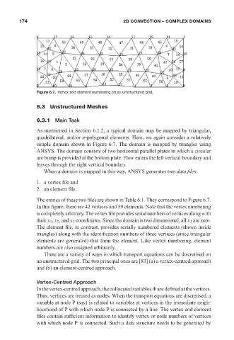
Figure 6.7. Vertex and element numbering on an unstructured grid. May 25, 2005 11:10
6.3 Unstructured Meshes
6.3.1 Main Task
As mentioned in Section 6.1.2, a typical domain may be mapped by triangular,
quadrilateral, and/or n-polygonal elements. Here, we again consider a relatively
simple domain shown in Figure 6.7. The domain is mapped by triangles using
ANSYS. The domain consists of two horizontal parallel plates in which a circular
arc bump is provided at the bottom plate. Flow enters the left vertical boundary and
leaves through the right vertical boundary.
When a domain is mapped in this way, ANSYS generates two data files:
1. a vertex file and
2. an element file.
The entries of these two files are shown in Table 6.1. They correspond to Figure 6.7.
In this figure, there are 42 vertices and 59 elements. Note that the vertex numbering
iscompletelyarbitrary.Thevertexfileprovidesserialnumbersofverticesalongwith
their x 1 , x 2 , and x 3 coordinates. Since the domain is two dimensional, all x 3 are zero.
The element file, in contrast, provides serially numbered elements (shown inside
triangles) along with the identification numbers of three vertices (since triangular
elements are generated) that form the element. Like vertex numbering, element
numbers are also assigned arbitrarily.
There are a variety of ways in which transport equations can be discretised on
an unstructured grid. The two principal ones are [83] (a) a vertex-centred approach
and (b) an element-centred approach.
Vertex-Centred Approach
In the vertex-centred approach, the collocated variables are defined at the vertices.
Thus, vertices are treated as nodes. When the transport equations are discretised, a
variable at node P (say) is related to variables at vertices in the immediate neigh-
bourhood of P with which node P is connected by a line. The vertex and element
files contain sufficient information to identify vertex or node numbers of vertices
with which node P is connected. Such a data structure needs to be generated by