
Page 197 - Introduction to Computational Fluid Dynamics
P. 197
P1: IWV
CB908/Date
0 521 85326 5
0521853265c06
176
2D CONVECTION – COMPLEX DOMAINS
T = T 1 May 25, 2005 11:10
JUNCTION
c 3 NODE
c 4
c 2
P T = T 2
c 5
c 1
(a) (b)
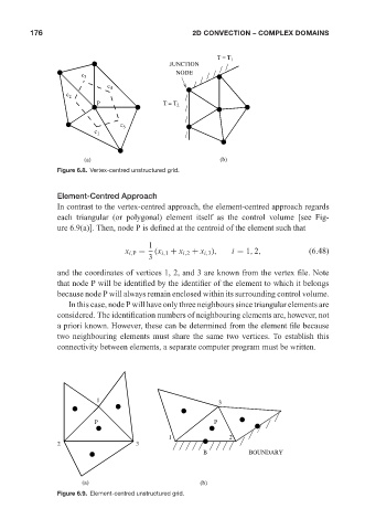
Figure 6.8. Vertex-centred unstructured grid.
Element-Centred Approach
In contrast to the vertex-centred approach, the element-centred approach regards
each triangular (or polygonal) element itself as the control volume [see Fig-
ure 6.9(a)]. Then, node P is defined at the centroid of the element such that
1
x i,P = (x i,1 + x i,2 + x i,3 ), i = 1, 2, (6.48)
3
and the coordinates of vertices 1, 2, and 3 are known from the vertex file. Note
that node P will be identified by the identifier of the element to which it belongs
because node P will always remain enclosed within its surrounding control volume.
In this case, node P will have only three neighbours since triangular elements are
considered. The identification numbers of neighbouring elements are, however, not
a priori known. However, these can be determined from the element file because
two neighbouring elements must share the same two vertices. To establish this
connectivity between elements, a separate computer program must be written.
1 3
P P
1 2
2 3
B BOUNDARY
(a) (b)
Figure 6.9. Element-centred unstructured grid.