
Page 201 - Introduction to Computational Fluid Dynamics
P. 201
P1: IWV
11:10
May 25, 2005
CB908/Date
0521853265c06
180
ξ 2 0 521 85326 5 2D CONVECTION – COMPLEX DOMAINS
NODES
b
n
E
2
FICTITIOUS
c POINTS
n
P 2
E
a 1 ξ 1
e E
P
P 1
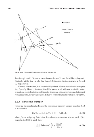
Figure 6.11. Construction of a line structure at cell face ab.
that through c at P 2 . Note that these intersections at P 1 and P 2 will be orthogonal.
Similarly, let the face-parallel line through E intersect the two normals at E 1 and
E 2 , respectively.
With this construction, it is clear that Equation 6.62 must be evaluated along the
line P 2 –c–E 2 . These evaluations, it will be appreciated, will now be similar to the
evaluations carried out at the cell face of a structured grid control volume. In the next
two subsections, the convective and diffusive contributions are evaluated separately.
6.3.4 Convective Transport
Following the usual methodology, the convective transport term in Equation 6.62
is evaluated as
]
+ (1 − f ck ) E 2 k , (6.63)
C ck ck = C ck [ f ck P 2
where f ck are weighting factors that depend on the convection scheme used. If, for
example, the UDS is used, then
|C ck |
f ck (UDS) = 0.5 1 + , (6.64)
C ck