
Page 103 - Introduction to Information Optics
P. 103
88 2. Signal Processing with Optics
2.4.5. HYBRID OPTICAL PROCESSING
It is trivial that a pure optical processor has certain severe constraints,
which make some processings difficult or even impossible to carry out.
Although an optical processor can be designed for specific purposes, it is
difficult to make it programmable as a digital computer. Another major
problem for optical processors is that they cannot make decisions as can their
electronic counterparts. In other words, some of the deficiencies of the optical
processor are the strong points of its electronic counterparts. For instance,
accuracy, controllability, and programmability are the trademarks of digital
computers. Thus, the concept of combining the optical system with its
electronic counterparts is rather natural as a means of applying the rapid
processing and parallelism of optics to a wider range of applications. We shall
now use this concept to illustrate a couple of microcomputer-based hybrid
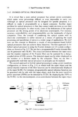
optical processors that can achieve these objectives. The first approach to the
hybrid optical processor is using the Fourier domain (or 4-f) system configur-
ation, as shown in Fig. 2.17. We see that a programmable Fourier domain filter
can be generated onto SLM2. The cross-convolution between the input scene
and the impulse response of the Fourier filter can be captured by a charge-
coupled device (CCD) camera. The detected signal can be either displayed on
the monitor or a decision made by the computer. Thus, we see that a
programmable real-time optical processor in principle can be realized.
The second approach to hybrid optical processing is using a joint transform
configuration, as shown in Fig. 2.18, in which both the input object and the
spatial impulse response of the filter function can be simultaneously displayed
at the input SLM1. For instance, programmable spatial reference function can
be generated side by side with the input object, such that the joint transform
power spectrum (JTPS) can be detected by CCD1. By displaying the JTPS on
the SLM2, via the microcomputer, cross-convolution between the input object
SLM SIM, CCD array
detector
Laser SF
CCD
Microcomputer
Fig. 2.17. A microcomputer-based FDP.