
Page 297 - Introduction to Information Optics
P. 297
282 5. Transformation with Optics
5.9. RADON TRANSFORM
The Radon transform describes projection operation in computed tomog-
raphy (CT), radio astronomy, and nuclear medicine [22]. In tomography the
object of interest is 3D, which is sliced by a set of planes of projection.
5.9.1, DEFINITION
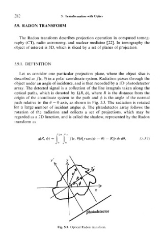
Let us consider one particular projection plane, where the object slice is
described as f(r, 9) in a polar coordinate system. Radiation passes through the
object under an angle of incidence, and is then recorded by a ID photodetector
array. The detected signal is a collection of the line integrals taken along the
optical paths, which is denoted by L(R, </>), where R is the distance from the
origin of the coordinate system to the path and (f> is the angle of the normal
path relative to the 9 = 0 axis, as shown in Fig. 5.3. The radiation is rotated
for a large number of incident angles 0. The phtodetector array follows the
rotation of the radiation and collects a set of projections, which may be
regarded as a 2D function, and is called the shadow, represented by the Radon
transform as
f(r, 8) -K]rdrde, (5.31)
photodetector
Fig, 5.3. Optical Radon transform.