
Page 328 - Introduction to Information Optics
P. 328
6.3. Thin-Film Waveguide Couplers
MEASURED
LEAST-MEAN
0.2t dB/em SOUARtS FIT
o 10
a
8500 A
•o
HI
I
510'
jio 3 0.58 dB/cm
5 6328 A
tc
20
Propagation Length (mm)
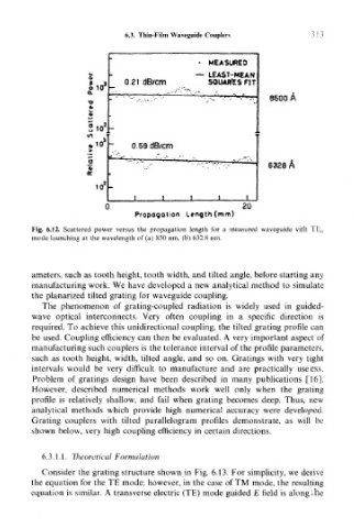
Fig. 6.12. Scattered power versus the propagation length for a measured waveguide with TE r
mode launching at the wavelength of (a) 850 nm, (b) 632.8 nm.
ameters, such as tooth height, tooth width, and tilted angle, before starting any
manufacturing work. We have developed a new analytical method to simulate
the planarized tilted grating for waveguide coupling.
The phenomenon of grating-coupled radiation is widely used in guided-
wave optical interconnects. Very often coupling in a specific direction is
required. To achieve this unidirectional coupling, the tilted grating profile can
be used. Coupling efficiency can then be evaluated. A very important aspect of
manufacturing such couplers is the tolerance interval of the profile parameters,
such as tooth height, width, tilted angle, and so on. Gratings with very tight
intervals would be very difficult to manufacture and are practically useless.
Problem of gratings design have been described in many publications [16].
However, described numerical methods work well only when the grating
profile is relatively shallow, and fail when grating becomes deep. Thus, new
analytical methods which provide high numerical accuracy were developed.
Grating couplers with tilted parallelogram profiles demonstrate, as will be
shown below, very high coupling efficiency in certain directions.
6.3.1.1. Theoretical Formulation
Consider the grating structure shown in Fig. 6.13. For simplicity, we derive
the equation for the TE mode; however, in the case of TM mode, the resulting
equation is similar. A transverse electric (TE) mode guided E field is along the