
Page 326 - Introduction to Information Optics
P. 326
6.2. Polymer Waveguides 3 1 I
waveguides fabricated. This method exploits the light streak scattered out of
the optical waveguide for the propagation-loss measurement. A prism-film
coupler is used to excite the desired guided mode. The waveguide under test is
mounted on a precise six-axis prism coupling stage. A optical stop is used to
prevent light scattered from the edge of the input prism from overlapping the
light streak. A laser-beam profile analyzer (such as the Spiricon LBA-100A) is
set to observe the light streak of the excited mode in the waveguide from the
front. The output video signal from the camera is analyzed by the system to
provide waveguide propagation loss.
The peak intensity variations along the streak can be determined by
scanning along the propagation direction, and the loss value can be directly
acquired from the longitudinal change. However, this 1-D scanning applies
only to the straight guides; also, setting the sampling line along the streak
requires precise adjustment. Therefore, transverse scan is performed repeating
the same procedure along the streak. This procedure provides a 2-D intensity
distribution.
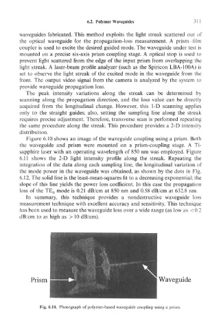
Figure 6.10 shows an image of the waveguide coupling using a prism. Both
the waveguide and prism were mounted on a prism-coupling stage. A Ti-
sapphire laser with an operating wavelength of 850 nm was employed. Figure
6.11 shows the 2-D light intensity profile along the streak. Repeating the
integration of the data along each sampling line, the longitudinal variation of
the mode power in the waveguide was obtained, as shown by the dots in Fig.
6.12. The solid line is the least-mean-squares fit to a decreasing exponential; the
slope of this line yields the power loss coefficient. In this case the propagation
loss of the TE 0 mode is 0.21 dB/cm at 850 nm and 0.58 dB/cm at 632.8 nm.
In summary, this technique provides a nondestructive waveguide loss
measurement technique with excellent accuracy and sensitivity. This technique
has been used to measure the waveguide loss over a wide range (as low as <0.2
dB/cm to as high as > 10 dB/cm).
Fig. 6.10. Photograph of polymer-based waveguide coupling using a prism.