
Page 571 - Introduction to Information Optics
P. 571
556 9. Computing with Optics
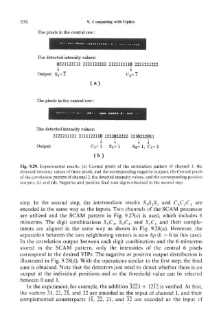
The pixels in the central row;
The detected intensity values;
0221122112 2221122222 2122112110 2221221222
Output: S 3=l C 2 =T
(a)
The pixels in the central row:
The detected intensity values:
2222211121 2111122110 1222022222 1210222011
* i I I
Output: C 3= 1 Si= 1 S«= 1, Ci= 1
(b)
Fig. 9.29. Experimental results, (a) Central pixels of the correlation pattern of channel 1, the
detected intensity values of these pixels, and the corresponding negative outputs, (b) Central pixels
of the correlation pattern of channel 2, the detected intensity values, and the corresponding positive
outputs, (c) and (d), Negative and positive final sum digits obtained in the second step.
step. In the second step, the intermediate results S 3S 2S 1 and C 3C 2C 1 are
encoded in the same way as the inputs. Two channels of the SCAM processor
are utilized and the SCAM pattern in Fig. 9.27(c) is used, which includes 6
minterms. The digit combinations S 3C 3, S 2C 2, and S^Cj and their comple-
ments are aligned in the same way as shown in Fig. 9.28(a). However, the
separation between the two neighboring vectors is now 6p (k = 6 in this case).
In the correlation output between each digit combination and the 6 minterms
stored in the SCAM pattern, only the intensities of the central 6 pixels
correspond to the desired VIPs. The negative or positive output distribution is
illustrated in Fig. 9.28(d). With the operations similar to the first step, the final
sum is obtained. Note that the detectors just need to detect whether there is an
output at the individual positions and so the threshold value can be selected
between 0 and 1.
In the experiment^ for example, the addition 3223 + 12T2 is verified. At first,
the vectors 31, 22, 21, and 32 are encoded as the input of channel 1, and their
complemented counterparts 3l, 22, 21, and 32 are encoded as the input of