
Page 570 - Introduction to Information Optics
P. 570
N
9.6. Optical Implementation !). 5
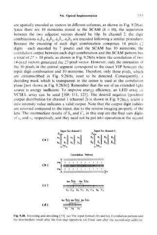
are spatially encoded as vectors in different columns, as shown in Fig. 9.28(a).
Since there are 10 minterms stored in the SCAM (k = 10), the separation
between the two adjacent vectors should be lOp. In channel 2, the digit
combinations a 3t> 3, a 2b 2, a lb l, a 0b Q are encoded following a similar procedure.
Because the encoding of each digit combination comprises 14 pixels (2
digits -each encoded by 7 pixels) and the SCAM has 10 minterms, the
correlation output between each digit combination and the SCAM pattern has
a total of 27 x 10 pixels, as shown in Fig. 9.28(b) where the correlation of two
14-pixel vectors generated the 27-pixel vector. However, only the intensities of
the 10 pixels in the central segment correspond to the exact VIP between the
input digit combination and 10 minterms. Therefore, only these pixels, which
are circumscribed in Fig. 9.28(b), need to be detected. Consequently, a
decoding mask which is transparent in the center is used at the correlation
plane [not shown in Fig. 9.28(b)]. Remember that the use of an extended light
source is energy inefficient. To improve energy efficiency, an LED array or
VCSEL array can be used [108-111, 125]. The desired negative (positive)
output distribution for channel 1 (channel 2) is shown in Fig. 9.28(c), where a
zero intensity value indicates a valid output. Note that the output digit indices
are reversed compared to the input, due to the reverse imaging property of the
lens. The intermediate results of S Q and C 5 in this step are the final sum digits
of ,s 0 and ,v 5, respectively, and they need not be put into operation in the second
Input for channel 1 Input for channel 2
(a)
Correlation Pattern
14q
(b)
14q i • • ! :
for 1(2) for 1(1)
(c) .. MH4.|MM. f>Hy"V,-'mt'
S>3 C4 Sj 03 Sj Cg
for 3(3) for 1(2) for 1(1)
(d)
S 3 s 2
Fig. 9.28. Encoding and decoding [73]. (a) The input format; (b) and (c), Correlation pattern and
the intermediate result after the first-step operation, (d) Final sum after the second-step addition.