
Page 572 - Introduction to Information Optics
P. 572
9.6. Optical Implementation
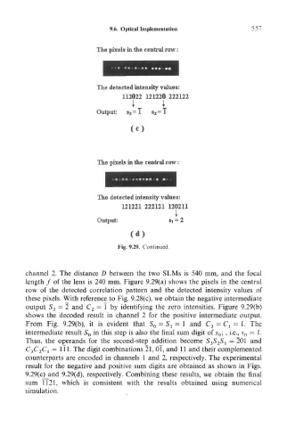
The pixels in lite central row:
The detected intensity values:
112022 121220 222122
i i
Output: s 3 =I $ 2 =I
The pixels in the central row:
The detected intensity values:
121221 222121 120211
Output: $t = 2
Fig. 9.29. Continued.
channel 2. The distance D between the two SLMs is 540 mm, and the focal
length / of the lens is 240 mm. Figure 9.29(a) shows the pixels in the central
row of the detected correlation pattern and the detected intensity values of
these pixels. With reference to Fig. 9.28(c), we obtain the negative intermediate
output S 3 = 2 and C 2 = 1 by identifying the zero intensities. Figure 9.29(b)
shows the decoded result in channel 2 for the positive intermediate output.
From Fig. 9.29(b), it is evident that S 0 = S l = 1 and C 3 = C, = 1. The
intermediate result S 0 in this step is also the final sum digit of s 0 ;, i.e., s 0 = 1.
Thus, the operands for the second-step addition become S 3S 2S 1 = 201 and
C 3C 2C l = ill. The digit combinations 21, Ol, and 11 and their complemented
counterparts are encoded in channels 1 and 2, respectively. The experimental
result for the negative and positive sum digits are obtained as shown in Figs.
9.29(c)_and 9.29(d), respectively. Combining these results, we obtain the final
sum TI21, which is consistent with the results obtained using numerical
simulation.