Page 622 - Introduction to Information Optics
P. 622
606                       10. Sensing with Optics
       length L = 2 mm. The dashed line corresponds to the weaker coupling case
                          4
       with An = 1.5 x 10""  and grating length L = 4 mm. From this figure, it can be
       seen that a higher reflectivity is achieved for the stronger coupling case.
       However, a narrower spectrum width could be achieved with a weaker
       coupling case, which is consistent with the conclusion given by Eq. (10.36).


          10.3,2,1.2. Fiber Bragg Grating Based Point Sensor
          From Eq. (10.30), we see that the reflected wavelength by Bragg grating, A B,
       is a function of both the effective refractive index of the fiber, n eff , and the
       Bragg grating period, A. Since both n eff and A may be affected by the change
       of strain and temperature on the fiber, A B is also sensitive to the change of
       strain and temperature on the fiber. Thus, by detecting the change in x, B, the
       strain and temperature can be sensed.
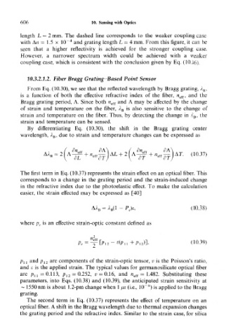
          By differentiating Eq. (10.30), the shift in the Bragg grating center
       wavelength, A B , due to strain and temperature changes can be expressed as


                                                                    (10.37)


       The first term in Eq. (10.37) represents the strain effect on an optical fiber. This
       corresponds to a change in the grating period and the strain-induced change
       in the refractive index due to the photoelastic effect. To make the calculation
       easier, the strain effected may be expressed as [40]

                                 AA B = A B(1 - PJe,                (1.0.38)

       where p e is an effective strain-optic constant defined as


                                                                    dO.39)


       p ll and p 12 are components of the strain-optic tensor, v is the Poisson's ratio,
       and £ is the applied strain. The typical values for germanosilicate optical fiber
       are p u = 0.113, p 12 = 0.252, v — 0.16, and n eff = 1.482. Substituting these
       parameters, into Eqs. (10.38) and (10.39), the anticipated strain sensitivity at
                                                     6
       ~ 1550 nm is about 1.2-pm change when 1 /j,e (i.e., 10~ ) is applied to the Bragg
       grating.
         The second term in Eq. (10.37) represents the effect of temperature on an
       optical fiber. A shift in the Bragg wavelength due to thermal expansion changes
       the grating period and the refractive index. Similar to the strain case, for silica

