
Page 626 - Introduction to Information Optics
P. 626
610 10. Sensing with Optics
Thus, such an unbalanced interferometer can detect tiny wavelength shift,
which makes the built fiber sensor have good sensitivity.
10.3.2.1.3, Quasi-Distributed fiber-Optic Sensors Based on
Fiber Bragg Gratings
The major motivation of applying fiber Bragg gratings to fiber sensors is the
capability of integrating a large number of fiber Bragg gratings in a single fiber
so that quasi-distributed fiber sensing can be realized in a compact and
cost-effective way [42]. Currently, with the rapid advent of optical communi-
cation networks, more than 100 wavelength channels can be put in a single
fiber by using the wavelength-division multiplexing (WDM) technique [43].
Thus, if we assign one central wavelength for each grating, more than 100
sensors can be integrated into a single fiber. Furthermore, applying time
division multiplexing (TDM) to each wavelength channel creates a severalfold
increase in the number of sensors that can be integrated. Therefore, a compact,
cost-effective distributed fiber sensor can be built.
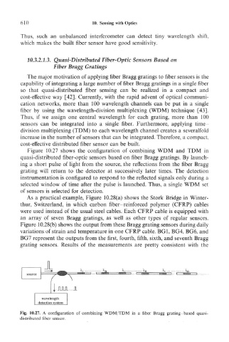
Figure 10.27 shows the configuration of combining WDM and TDM in
quasi-distributed fiber-optic sensors based on fiber Bragg gratings. By launch-
ing a short pulse of light from the source, the reflections from the fiber Bragg
grating will return to the detector at successively later times. The detection
instrumentation is configured to respond to the reflected signals only during a
selected window of time after the pulse is launched. Thus, a single WDM set
of sensors is selected for detection.
As a practical example, Figure 10.28(a) shows the Stork Bridge in Winter-
thur, Switzerland, in which carbon fiber-reinforced polymer (CFRP) cables
were used instead of the usual steel cables. Each CFRP cable is equipped with
an array of seven Bragg gratings, as well as other types of regular sensors.
Figure 10.28(b) shows the output from these Bragg grating sensors during daily
variations of strain and temperature in one CFRP cable. BG1, BG4, BG6, and
BG7 represent the outputs from the first, fourth, fifth, sixth, and seventh Bragg
grating sensors. Results of the measurements are pretty consistent with the
Fig. 10.27. A configuration of combining WDM/TDM in a fiber Bragg grating-based quasi-
distributed fiber sensor.