
Page 623 - Introduction to Information Optics
P. 623
10.3. Distributed Fiber-Optic Sensors 607
fiber, this wavelength shift due to the temperature change may be expressed as
[40]
AA B = A B(« A + aJAT; {10.40)
where a A = (l/A)(5A/dT) is the thermal expansion coefficient and a n =
(l/n eff )(dn eff /dT) represents the thermo-optic coefficient. For the fiber Bragg
6
6
grating, « A « 0.55 x 10~ /°C and a,, a 8.6 x 10~ /°C. Thus, the thermo-optic
effect is the dominant effect for the wavelength shift of the Bragg grating when
there is a temperature change on the grating. Based on Eq. (10.40), the expected
temperature sensitivity for a 1550-nm Bragg grating is approximately 13.7
pm/°C.
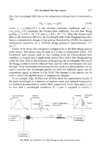
Figure 10.24 shows the conceptual configuration of the fiber Bragg grating
point sensor. This sensor may be used as a strain or temperature sensor. The
broadband light source, such as that coming from an erbium-doped fiber
amplifier, is coupled into a single mode optical fiber with a fiber Bragg grating
inside the fiber. Due to the existence of the grating, the wavelengths that match
the Bragg condition will be reflected back and the other wavelengths will pass
through. Then wavelength monitoring devices (such as a spectrometer) can be
used to monitor the wavelength spectra for both the reflected signal and the
transmitted signal, as shown in Fig. 10.24. The changes in the spectra can be
used to detect the applied strain or temperature changes.
As an example, Figs. 10.25(a) and 10.25(b) show the experimental results of
the peak wavelength as a function of applied strain and ambient temperature
for standard germanosilicate optical fiber, respectively. From these data, it can
be seen that a wavelength resolution of ~ 1 pm is required to resolve a
input braodband reflected origninal transmitted
spectrum component " signal
rain or temperature shifted
ihifted induced shift
Fig. 10.24. An illustration of a fiber Bragg grating -based point sensor.