
Page 621 - Introduction to Information Optics
P. 621
10.3. Distributed Fiber-Optic Sensors 605
factor A/j = 0. Thus, the peak reflectivity of the Bragg grating is
2
R(L, A B) = tanh (QL). (10.35)
From Eq. (10.35), it can be seen that the peak reflectivity increases as the
refractive index modulation depth, An, and/or grating length L increases.
A general expression for the approximate full-width-half-maximum band-
width of the grating is given by [39]
(10.36)
where q is a parameter that approximately equals 1 for strong gratings (with
near 100% reflection) whereas q ~ 0.5 for weak gratings.
Equation (10.36) shows that, to achieve narrow spectral width, long grating
length and small refractive index modulation need to be used.
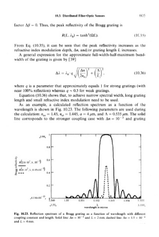
As an example, a calculated reflection spectrum as a function of the
wavelength is shown in Fig. 10.23. The following parameters are used during
the calculation: n co = 1.45, n cl = 1.445, a = 4/mi, and A = 0.535 /un. The solid
3
line corresponds to the stronger coupling case with An = 10" and grating
,.0.99.,
,X,10
R(4-10 ,X,0.15xIO'
,4.1 16x10
wavelength in micron
Fig. 10.23. Reflection spectrum of a Bragg grating as a function of wavelength with different
3
coupling constant and length. Solid line: M = 10~ and L = 2mm; dashed line: An = 1.5 x 10 4
and L = 4 mm.