
Page 639 - Introduction to Information Optics
P. 639
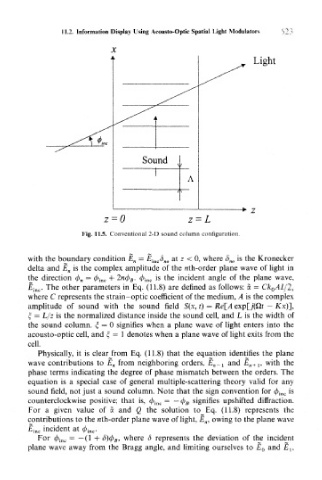
11.2. Information Display Using Acousto-Optic Spatial Light Modulators
                            X
                                                                Light


                                    Sound
                                               A


                                                            -> z
                          z=0                  z = L
                    Fig. 11.5. Conventional 2-D sound column configuration.


       with the boundary condition E n = E inc6 no at z < 0, where b no is the Kronecker
       delta and £„ is the complex amplitude of the nth-order plane wave of light in
       the direction (j) n = ^> inc + 2ncf) B. cf) inc is the incident angle of the plane wave,
       £ inc. The other parameters in Eq. (11.8) are defined as follows: a = Ck 0AL/2,
       where C represents the strain-optic coefficient of the medium, A is the complex
       amplitude of sound with the sound field S(x, t) = Re[A exp[j'(£li — Kx)],
       £ = L/z is the normalized distance inside the sound cell, and L is the width of
       the sound column, £ = 0 signifies when a plane wave of light enters into the
       acousto-optic cell, and £, = 1 denotes when a plane wave of light exits from the
       cell.
         Physically, it is clear from Eq. (11.8) that the equation identifies the plane
       wave contributions to E n from neighboring orders, £„_  1 and E n+l, with the
       phase terms indicating the degree of phase mismatch between the orders. The
       equation is a special case of general multiple-scattering theory valid for any
       sound field, not just a sound column. Note that the sign convention for cj6 ine is
       counterclockwise positive; that is, $ inc = — </> B signifies upshifted diffraction.
       For a given value of a and Q the solution to Eq. (11.8) represents the
       contributions to the nth-order plane wave of light, E n, owing to the plane wave
       £ inc incident at <^> inc.
         For (f> inc = — (1 + d)(f) B, where 6 represents the deviation of the incident
       plane wave away from the Bragg angle, and limiting ourselves to £ 0 and £,,