
Page 701 - Introduction to Information Optics
P. 701
12.2. Optical Network Elements 685
-10
-20
Q.
E
< -30
-40
-50
192.0T 192.2T 192.41 192.6T 192.8T 193.0T 193.2T
Frequency (Hz)
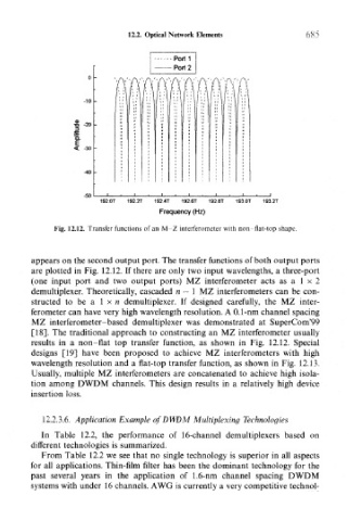
Fig. 12.12. Transfer functions of an M Z interferometer with non-flat-top shape.
appears on the second output port. The transfer functions of both output ports
are plotted in Fig. 12.12. If there are only two input wavelengths, a three-port
(one input port and two output ports) MZ interferometer acts as a 1 x 2
demultiplexer. Theoretically, cascaded n — 1 MZ interferometers can be con-
structed to be a 1 x n demultiplexer. If designed carefully, the MZ inter-
ferometer can have very high wavelength resolution. A 0.1-nm channel spacing
MZ interferometer-based demultiplexer was demonstrated at SuperCorn'99
[18]. The traditional approach to constructing an MZ interferometer usually
results in a non-flat top transfer function, as shown in Fig. 12.12. Special
designs [19] have been proposed to achieve MZ interferometers with high
wavelength resolution and a flat-top transfer function, as shown in Fig. 12.13.
Usually, multiple MZ interferometers are concatenated to achieve high isola-
tion among DWDM channels. This design results in a relatively high device
insertion loss.
12.2.3.6. Application Example of DWDM Multiplexing Technologies
In Table 12.2, the performance of 16-channel demultiplexers based on
different technologies is summarized.
From Table 12.2 we see that no single technology is superior in all aspects
for all applications. Thin-film filter has been the dominant technology for the
past several years in the application of 1.6-nm channel spacing DWDM
systems with under 16 channels. AWG is currently a very competitive technol-