
Page 700 - Introduction to Information Optics
P. 700
12. Networking with Optics
star couplers are designed in such way that at one specific output port only
one particular wavelength is constructively interfered. As a result, the multiple
wavelengths from the input of the AWG are demultiplexed.
After decades of intensive worldwide research, the AWG-based DWDM
device has achieved performance suitable for commercial application. Its main
drawback is that its poor temperature coefficient requires an active tempera-
ture controller, which adds an additional bundle to network management.
Nevertheless, AWG takes advantage of silicon optical bench waveguide tech-
nology and can be manufactured in large quantities at one time. It is a
cost-effective solution for a single chip handling many channels.
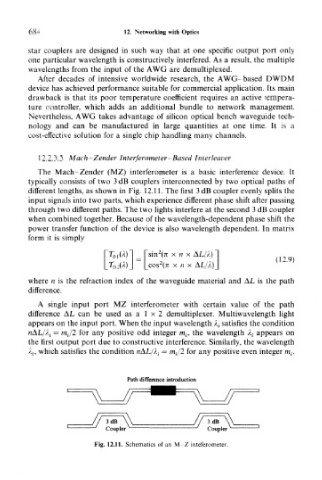
12,2.3.5. Mach—Zender Interferometer-Based Interleaver
The Mach-Zender (MZ) interferometer is a basic interference device. It
typically consists of two 3 dB couplers interconnected by two optical paths of
different lengths, as shown in Fig. 12.11. The first 3 dB coupler evenly splits the
input signals into two parts, which experience different phase shift after passing
through two different paths. The two lights interfere at the second 3 dB coupler
when combined together. Because of the wavelength-dependent phase shift the
power transfer function of the device is also wavelength dependent. In matrix
form it is simply
2
sin (7i x n x AL/A)
(12.9)
2
cos (7i x n x AL/A)
where n is the refraction index of the waveguide material and AL is the path
difference,
A single input port MZ interferometer with certain value of the path
difference AL can be used as a 1 x 2 demultiplexer. Multiwavelength light
appears on the input port. When the input wavelength A { satisfies the condition
nAL/A,- = m-J2 for any positive odd integer m,-, the wavelength A,- appears on
the first output port due to constructive interference. Similarly, the wavelength
A,-, which satisfies the condition nAL/A,- = m,-/2 for any positive even integer m f .
Path difference introduction
Fig. 12.11. Schematics of an M-Z inteferometer.