
Page 703 - Introduction to Information Optics
P. 703
12.2. Optical Network Elements 687
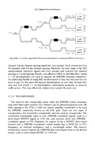
Fig. 12.14. A scalable, upgradable 80-channel demultiplexer combining different technologies.
channel, 0.4-nm channel spacing signal into two streams. Each stream now has
40 channels with 0.8 nm channel spacing. Similarly, the next stage of the MZ
interferometer separates signals into four streams and converts the channel
spacing to 1.6-nm spacing. Finally, cost-effective AWG or thin-film filter-based
1 x 20 demultiplexers are used to separate all DWDM channels completely.
An additional benefit of using MZ interferometers is that the end users do not
have to pay for the entire 80-channel demultiplexer at one time. Instead they
may buy and install 1 x 20 demultiplexer submodules gradually as network
traffic grows. This may effectively reduce total system life-cycle cost.
12.2.4. TRANSPONDER
The need for the transponder arises when the DWDM system interfaces
with other fiber-optic systems. ITU defined a set of optical frequencies with 100
GHz spacing in the 1530 to 1620 nm optical amplifier bandwidth to be used
for DWDM, commonly known as the ITU grid. There are two types of
transponders, the transmitter transponder and the receiver transponder. The
transmitter transponder takes in non-DWDM-complaint signals, such as a
short-reach SONET signal at 1310 nm, and converts them into DWDM
complaint signals at ITU frequency for output. It has a SONET short-reach
receiver and a DWDM transmitter, which usually has a DFB LD at ITU
frequency, an external modulator, and a wavelength locker. The receiver
transponder receives signals off a DWDM link and outputs them at the desired
format, such as short-reach SONET at 1310 nm.