
Page 702 - Introduction to Information Optics
P. 702
12. Networking with Optics
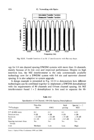
• Simulated Transfer Function
• Measured Transfer Function
193.00T 193.20T 193.40T 193.60T 193.80T
Frequency (Hz)
Fig. 12.13. Transfer function of an M Z interferometer with flat-top shape.
ogy for 0.8 nm channel spacing DWDM systems with more than 16 channels,
mainly because of its low cost and improved performance. Despite its high
insertion loss, the MZ interferometer is the only commercially available
technology now for a DWDM system with 0.4 nm and narrower channel
spacing. It is also adaptive to system upgrade.
A design example is presented in Fig. 12.14 to demonstrate how different
technologies can be combined together to implement a DWDM demultiplexer
with the requirements of 80 channels and 0.4-nm channel spacing. An MZ
interferometer-based 1x 2 demultiplexer is first used to separate the 80-
Table 12.2
Specification of 16-Channel, 100-GHz Spacing Demultiplexers
Thin-film Bulk Special 1x 2
Technologies filter AWG grating MZI
0.5 dB BW (nm) 0.2 0.2 0.2 0.25
Insertion loss 8dB 9dB 6dB 6dB
Isolation >22dB > 22 dB >35 dB >30dB
PDL 0.1 dB <0.5 dB <0.5 dB 0.2 dB
Spacing narrower than No No No Yes
0,4 nm
Cost Medium Low Low High
Source: Optical Fiber Conference 1999 and 2000.