
Page 695 - Introduction to Information Optics
P. 695
12.2. Optical Network Elements
Optical Fiber
D
M E
U M
X U
.X
Fig. 12.5. A simple DWDM optical transmission system.
more channels can be multiplexed into a single fiber. This puts DWDM
multiplexer/demultiplexer technology at the forefront from the system point of
view since ultimately its performance defines how many channels can be
utilized in one fiber.
12.2.3.1, Key Parameters of DWDM Multiplexer/Demultiplexer
A multiplexer device requires a wavelength-selective mechanism that can be
implemented using common technologies, including the interference filter, bulk
grating, array waveguide grating (AWG), and Mach-Zehnder (MZ) inter-
ferometer. Before comparing different enabling technologies, we first introduce
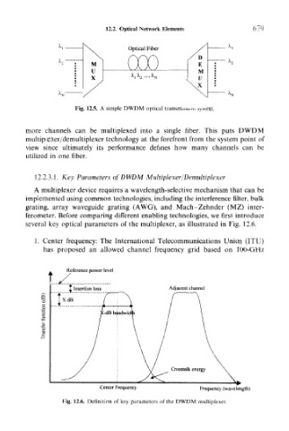
several key optical parameters of the multiplexer, as illustrated in Fig. 12.6,
1. Center frequency: The International Telecommunications Union (ITU)
has proposed an allowed channel frequency grid based on 100-GHz
Reference power level
1 Insertion loss Adjacent channel
TxdB
Center Frequency Frequency (wavelength)
Fig. 12.6. Definition of key parameters of the DWDM multiplexer.