
Page 83 - Introduction to Microcontrollers Architecture, Programming, and Interfacing of The Motorola 68HC12
P. 83
60 Chapter 3 Addressing Modes
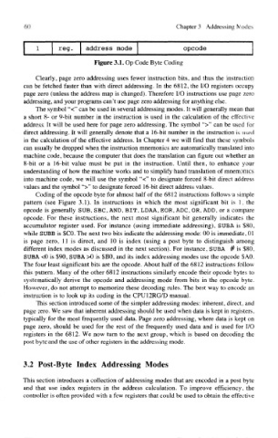
Figure 3.1. Op Code Byte Coding
Clearly, page zero addressing uses fewer instruction bits, and thus the instruction
can be fetched faster than with direct addressing. In the 6812, the I/O registers occupy
page zero (unless the address map is changed). Therefore I/O instructions use page zero
addressing, and your programs can't use page zero addressing for anything else.
The symbol "<" can be used in several addressing modes. It will generally mean that
a short 8- or 9-bit number in the instruction is used in the calculation of the effective
address. It will be used here for page zero addressing. The symbol ">" can be used for
direct addressing. It will generally denote that a 16-bit number in the instruction is used
in the calculation of the effective address. In Chapter 4 we will find that these symbols
can usually be dropped when the instruction mnemonics are automatically translated into
machine code, because the computer that does the translation can figure out whether an
8-bit or a 16-bit value must be put in the instruction. Until then, to enhance your
understanding of how the machine works and to simplify hand translation of mnemonics
into machine code, we will use the symbol "<" to designate forced 8-bit direct address
values and the symbol ">" to designate forced 16-bit direct address values.
Coding of the opcode byte for almost half of the 6812 instructions follows a simple
pattern (see Figure 3.1). In instructions in which the most significant bit is 1, the
opcode is generally SUB, SBC, AND, BIT, LDAA, EOR, ADC, OR, ADD, or a compare
opcode. For these instructions, the next most significant bit generally indicates the
accumulator register used. For instance (using immediate addressing), SUBA is $80,
while SUBB is $CO. The next two bits indicate the addressing mode: 00 is immediate, 01
is page zero, 11 is direct, and 10 is index (using a post byte to distinguish among
different index modes as discussed in the next section). For instance, SUBA # is $80,
SUBA <0 is $90, SUBA >0 is $BO, and its index addressing modes use the opcode $AO,
The four least significant bits are the opcode. About half of the 6812 instructions follow
this pattern. Many of the other 6812 instructions similarly encode their opcode bytes to
systematically derive the opcode and addressing mode from bits in the opcode byte.
However, do not attempt to memorize these decoding rules. The best way to encode an
instruction is to look up its coding in the CPU12RG/D manual.
This section introduced some of the simpler addressing modes: inherent, direct, and
page zero. We saw that inherent addressing should be used when data is kept in registers,
typically for the most frequently used data. Page zero addressing, where data is kept on
page zero, should be used for the rest of the frequently used data and is used for I/O
registers in the 6812. We now turn to the next group, which is based on decoding the
post byte and the use of other registers in the addressing mode.
3.2 Post-Byte Index Addressing Modes
This section introduces a collection of addressing modes that are encoded in a post byte
and that use index registers in the address calculation. To improve efficiency, the
controller is often provided with a few registers that could be used to obtain the effective