
Page 86 - Introduction to Microcontrollers Architecture, Programming, and Interfacing of The Motorola 68HC12
P. 86
3.2 Post Byte Index Addressing Modes 63
Figure 33, Program Segment to Add Two Bytes Using Vector Indexing
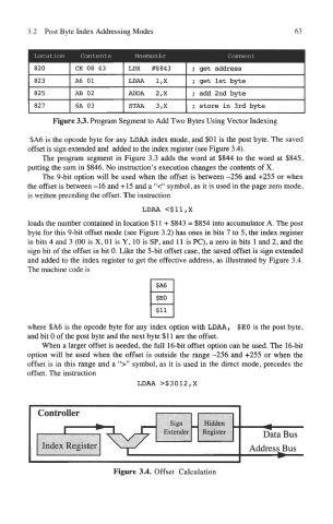
$A6 is the opcode byte for any LDAA index mode, and $01 is the post byte. The saved
offset is sign extended and added to the index register (see Figure 3.4).
The program segment in Figure 3.3 adds the word at $844 to the word at $845,
putting the sum in $846. No instruction's execution changes the contents of X.
The 9-bit option will be used when the offset is between -256 and +255 or when
the offset is between -16 and +15 and a "<" symbol, as it is used in the page zero mode,
is written preceding the offset. The instruction
LDAA <$11,X
loads the number contained in location $11+ $843 = $854 into accumulator A. The post
byte for this 9-bit offset mode (see Figure 3.2) has ones in bits 7 to 5, the index register
in bits 4 and 3 (00 is X, 01 is Y, 10 is SP, and 11 is PC), a zero in bits 1 and 2, and the
sign bit of the offset in bit 0. Like the 5-bit offset case, the saved offset is sign extended
and added to the index register to get the effective address, as illustrated by Figure 3.4.
The machine code is
where $A6 is the opcode byte for any index option with LDAA, $EO is the post byte,
and bit 0 of the post byte and the next byte $11 are the offset.
When a larger offset is needed, the full 16-bit offset option can be used. The 16-bit
option will be used when the offset is outside the range -256 and +255 or when the
offset is in this range and a ">" symbol, as it is used in the direct mode, precedes the
offset. The instruction
LDAA >$3012,X
Figure 3.4. Offset Calculation