
Page 138 - Introduction to Petroleum Engineering
P. 138
ACOUSTIC IMPEDANCE AND REFLECTION COEFFICIENTS 125
Layer 1 Z , , V P1
1
B1
Layer 2 Z , , V P2
2
B2
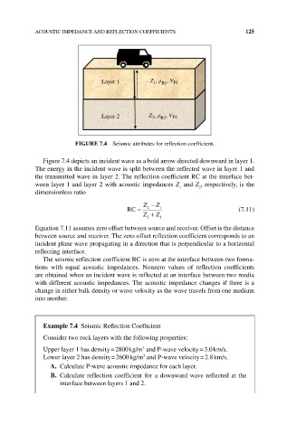
FIGuRE 7.4 Seismic attributes for reflection coefficient.
Figure 7.4 depicts an incident wave as a bold arrow directed downward in layer 1.
The energy in the incident wave is split between the reflected wave in layer 1 and
the transmitted wave in layer 2. The reflection coefficient RC at the interface bet-
ween layer 1 and layer 2 with acoustic impedances Z and Z , respectively, is the
1
2
dimensionless ratio
Z − Z
RC = 2 1 (7.11)
Z 2 + Z 1
Equation 7.11 assumes zero offset between source and receiver. Offset is the distance
between source and receiver. The zero offset reflection coefficient corresponds to an
incident plane wave propagating in a direction that is perpendicular to a horizontal
reflecting interface.
The seismic reflection coefficient RC is zero at the interface between two forma-
tions with equal acoustic impedances. Nonzero values of reflection coefficients
are obtained when an incident wave is reflected at an interface between two media
with different acoustic impedances. The acoustic impedance changes if there is a
change in either bulk density or wave velocity as the wave travels from one medium
into another.
Example 7.4 Seismic Reflection Coefficient
Consider two rock layers with the following properties:
Upper layer 1 has density = 2800 kg/m and P‐wave velocity = 3.0 km/s.
3
Lower layer 2 has density = 2600 kg/m and P‐wave velocity = 2.8 km/s.
3
A. Calculate P‐wave acoustic impedance for each layer.
b. Calculate reflection coefficient for a downward wave reflected at the
interface between layers 1 and 2.