
Page 207 - Introduction to Petroleum Engineering
P. 207
194 WELL COMPLETIONS
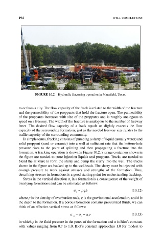
FIGURE 10.2 Hydraulic fracturing operation in Mansfield, Texas.
to or from a city. The flow capacity of the frack is related to the width of the fracture
and the permeability of the proppants that hold the fracture open. The permeability
of the proppants increases with size of the proppants and is roughly analogous to
speed on a freeway. The width of the fracture is analogous to the number of freeway
lanes. The desired flow capacity of a frack equals or slightly exceeds the flow
capacity of the surrounding formation, just as the needed freeway size relates to the
traffic capacity of the surrounding community.
In simple terms, fracking consists of pumping a slurry of liquid (usually water) and
solid proppant (sand or ceramic) into a well at sufficient rate that the bottom‐hole
pressure rises to the point of splitting and then propagating a fracture into the
formation. A fracking operation is shown in Figure 10.2. Storage containers shown in
the figure are needed to store injection liquids and proppant. Trucks are needed to
blend the mixture to form the slurry and pump the slurry into the well. The trucks
shown in the figure are backed up to the wellheads. The slurry must be injected with
enough pressure to work against stresses and strengths of the formation. Thus,
describing stresses in formations is a good starting point for understanding fracking.
Stress in the vertical direction σ in a formation is a consequence of the weight of
v
overlying formations and can be estimated as follows:
σ = ρgh (10.12)
v
where ρ is the density of overburden rock, g is the gravitational acceleration, and h is
the depth to the formation. If a porous formation contains pressurized fluids, we can
think of an effective vertical stress as follows:
σ = σ −α p (10.13)
ve
v
in which p is the fluid pressure in the pores of the formation and α is Biot’s constant
with values ranging from 0.7 to 1.0. Biot’s constant approaches 1.0 for modest to