
Page 219 - Introduction to Petroleum Engineering
P. 219
206 UPSTREAM FACILITIES
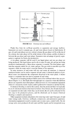
Pressure gauge
Wing valve
Swab valve
Wing
Master valve
Flow line
Tubing head
Wellhead
Casing head
FIgURE 11.1 Christmas tree and wellhead.
Fluids flow from the wellhead assembly to separation and storage facilities.
Separators are used to separate gas, oil, and water phases based on fluid density. If
gas, oil, and water phases are in a vertical column, the gas phase will be at the top of
the column, the water phase will be at the bottom of the column, and the oil phase is
between the gas phase and water phase. Separators take advantage of gravity segre-
gation to separate the fluids after production.
A two‐phase separator will be used if one liquid phase and one gas phase are
being produced. The liquid phase can be oil or water. If water, oil, and gas are being
produced simultaneously, a three‐phase separator is needed. The three‐phase sepa-
rator has separate outlets for oil, water, and gas. The gas outlet is near the top of the
separator, while the water outlet is near the bottom of the separator.
In some instances oil and water will mix and create an emulsion. A chemical
emulsion breaker can be used to separate oil and water. A chemical analysis of pro-
duced water can determine the compounds dissolved in the water phase. A heater
treater is a separator that uses heat to separate oil and water.
The process of treating produced fluids starts at the wellhead where they are pro-
duced (Figure 11.2). The fluids flow through pipes to a separator where the different
phases are separated. Each fluid phase is then moved to its own treatment equipment
where it is measured, tested, treated, and/or gathered for transport to another facility.
If chemical flooding is used in the system, then the produced fluid will typically
be an oil–chemical emulsion that must be broken. Once broken, the oil and chemicals
are separated out into tanks where they can be tested, the oil can be collected for the
next step in the production process, and the chemicals can be reused. Chemical
flooding is complex and expensive.
Other equipment includes dehydrators (for removing water vapor from gas), oil and
water storage tanks, flowlines, wellheads, compressors, and automation equipment.
Automation equipment is used to monitor and, in some cases, control wells. On‐site
storage tanks store produced oil and water until the liquids can be transported away