
Page 116 - Introduction to Transfer Phenomena in PEM Fuel Cells
P. 116
O
2
agg
6 n ⋅
=−
j
c
c
O
2
R
2
agg
e− ⋅ F ⋅ D agg c ⋅ agg ⋅ Mass Transfer Phenomena 105
j ⋅ S 0.5 × F
0
1 − R ⋅ c a ⋅ exp − ⋅ η c ⋅
agg 2F c ref D agg ⋅ RT [3.51]
⋅
⋅⋅
O 2 O 2
j ⋅ S 0.5 × F
0
coth R agg ⋅ c a ⋅ exp − ⋅ η c
⋅
⋅⋅
2F c ref D agg ⋅ RT
O 2 O 2
e
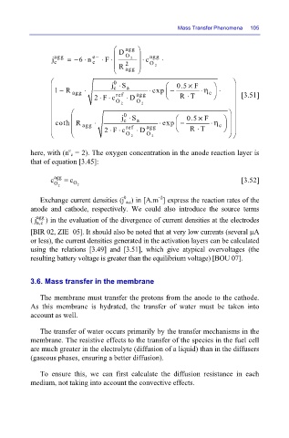
here, with (n c = 2). The oxygen concentration in the anode reaction layer is
that of equation [3.45]:
c agg = c [3.52]
O 2 O 2
0
–2
Exchange current densities (j a,c) in [A.m ] express the reaction rates of the
anode and cathode, respectively. We could also introduce the source terms
( j agg ) in the evaluation of the divergence of current densities at the electrodes
a,c
[BIR 02, ZIE 05]. It should also be noted that at very low currents (several µA
or less), the current densities generated in the activation layers can be calculated
using the relations [3.49] and [3.51], which give atypical overvoltages (the
resulting battery voltage is greater than the equilibrium voltage) [BOU 07].
3.6. Mass transfer in the membrane
The membrane must transfer the protons from the anode to the cathode.
As this membrane is hydrated, the transfer of water must be taken into
account as well.
The transfer of water occurs primarily by the transfer mechanisms in the
membrane. The resistive effects to the transfer of the species in the fuel cell
are much greater in the electrolyte (diffusion of a liquid) than in the diffusers
(gaseous phases, ensuring a better diffusion).
To ensure this, we can first calculate the diffusion resistance in each
medium, not taking into account the convective effects.