
Page 157 - Introduction to Transfer Phenomena in PEM Fuel Cells
P. 157
146 Introduction to Transfer Phenomena in PEM Fuel Cells
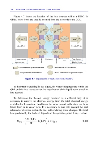
Figure 4.7 shows the location of the heat sources within a PEFC. In
GDLs, water flows are usually oriented from the electrode to the GDL.
Figure 4.7. Expressions of heat sources in a PEMFC
To illustrate everything in this figure, the water changing state within the
GDL and the heat necessary for the vaporization of the liquid water are taken
into account.
To determine the thermal energy produced in a different way, it is
necessary to remove the electrical energy from the total chemical energy
available for the reaction. In addition, the water present in the stack can be in
liquid form or in vapor form. It is necessary to take into account the heat
released or absorbed within the fuel cell of during phase changes. The total
heat produced by the fuel cell depends on the operating point. It is given by:
Δ ( hT,P )
+
Q total = − E (T,P ⋅ J Q H O [4.42]
)
2F 2