
Page 161 - Introduction to Transfer Phenomena in PEM Fuel Cells
P. 161
150 Introduction to Transfer Phenomena in PEM Fuel Cells
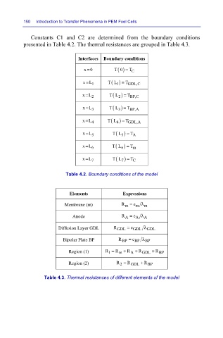
Constants C1 and C2 are determined from the boundary conditions
presented in Table 4.2. The thermal resistances are grouped in Table 4.3.
Interfaces Boundary conditions
=
() =
x0 T0 T
C
=
xL TL ) = T GDL,C
1
( 1
(
=
xL TL 2 ) = T BP,C
2
=
xL TL ) = T BP,A
( 3
3
(
=
xL TL 4 ) = T GDL,A
4
=
xL TL ) = T
( 5
5
A
(
=
xL TL 6 ) = T
6
m
=
xL TL ) = T
C
( 7
7
Table 4.2. Boundary conditions of the model
Elements Expressions
Membrane (m) R m = e m λ m
Anode R A = e A λ A
Diffusion Layer GDL R GDL = e GDL λ GDL
Bipolar Plate BP R BP = e BP λ BP
Region (1) R = R m + R A + R GDL + R BP
1
Region (2) R = R GDL + R BP
2
Table 4.3. Thermal resistances of different elements of the model