
Page 158 - Introduction to Transfer Phenomena in PEM Fuel Cells
P. 158
Heat Transfer Phenomena 147
where:
(
– hT,PΔ
liquid form; ) is the enthalpy of the reaction when water is produced in
– ( ) is the voltage at the terminals of the fuel cell (function of J);
ET,P
– Q HO is the amount of heat resulting from the phase changes of water;
2
– J is the current delivered, in [A].
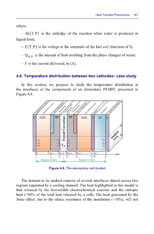
4.6. Temperature distribution between two cathodes: case study
In this section, we propose to study the temperature distribution at
the interfaces of the components of an elementary PEMFC presented in
Figure 4.8.
Figure 4.8. The elementary cell studied
The domain to be studied consists of several interfaces shared across two
regions separated by a cooling channel. The heat highlighted in this model is
that released by the irreversible electrochemical reaction and the entropic
heat (~90% of the total heat released by a cell). The heat generated by the
Joule effect, due to the ohmic resistance of the membrane (~10%), will not