
Page 159 - Introduction to Transfer Phenomena in PEM Fuel Cells
P. 159
148 Introduction to Transfer Phenomena in PEM Fuel Cells
be considered in this case study. This heat is located at the cathode of each
heat source region; it will be transferred by thermal conduction through the
different layers of the cell to the heat sink (cooling channel).
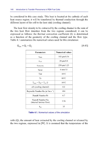
The heat flow density to be extracted by the cooling channel is the sum of
the two heat flow densities from the two regions considered; it can be
expressed as follows: the thermal convection coefficient (h) is determined
as a function of the geometry of the cooling channel and the flow type.
Table 4.1 summarizes the numerical values used for this simulation:
Q ext = Q + Q 2 [4.43]
1
Parameters Numerical values
e m/m 183 µm/0.36
e A/A 20 µm/0.8
e GDL/GDL 250 µm/1.25
e BP/BP 6 mm/15
Tair 30°C
Tc 80°C
T moy = T BP + T air /2 54°C
a/b (cooling channel) 6/2
–1
Reynolds Number Re (at 3m.s ) 494
Prandtl Number Pr 0.7
Nusselt Number Nu
(internal laminar flow) 3.96
h air 35
Table 4.1. Numerical values of the simulation
with (Q), the amount of heat extracted by the cooling channel or released by
the two regions, expressed in [W]. It is assumed that the temperature of the