
Page 97 - Introduction to Transfer Phenomena in PEM Fuel Cells
P. 97
86 Introduction to Transfer Phenomena in PEM Fuel Cells
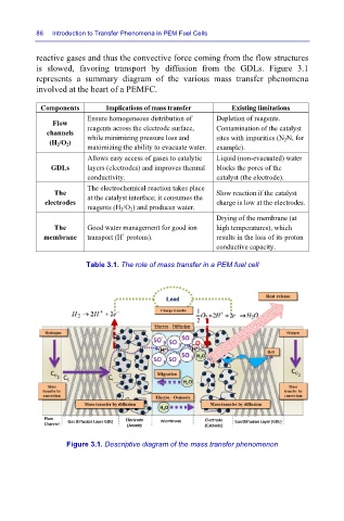
reactive gases and thus the convective force coming from the flow structures
is slowed, favoring transport by diffusion from the GDLs. Figure 3.1
represents a summary diagram of the various mass transfer phenomena
involved at the heart of a PEMFC.
Components Implications of mass transfer Existing limitations
Ensure homogeneous distribution of Depletion of reagents.
Flow
channels reagents across the electrode surface, Contamination of the catalyst
while minimizing pressure loss and
sites with impurities (N 2 N, for
(H 2 /O 2 )
maximizing the ability to evacuate water. example).
Allows easy access of gases to catalytic Liquid (non-evacuated) water
GDLs layers (electrodes) and improves thermal blocks the pores of the
conductivity. catalyst (the electrode).
The electrochemical reaction takes place
The Slow reaction if the catalyst
electrodes at the catalyst interface; it consumes the charge is low at the electrodes.
reagents (H 2 /O 2 ) and produces water.
Drying of the membrane (at
The Good water management for good ion high temperatures), which
+
membrane transport (H protons). results in the loss of its proton
conductive capacity.
Table 3.1. The role of mass transfer in a PEM fuel cell
Figure 3.1. Descriptive diagram of the mass transfer phenomenon