
Page 333 - Sami Franssila Introduction to Microfabrication
P. 333
312 Introduction to Microfabrication
Heating (and cooling) can also be affected by direct
Clean
atm press resist APCVD th oxid backside contact with a fluid. Argon is employed in
10 2 epi sputtering systems to ramp up wafers to 400 to 500 C,
◦
in a timescale of 10 s. In etchers, the wafer backside is
10 PECVD LPCVD often cooled by helium flow. Some of these gases leak
RIE poly, ox/nitr, metal into the process chamber, and the type of heating/cooling
Cryo MIE Sputt-dep gas has to be compatible with the process. In a plasma
Pressure (torr) 10 −4 ECR UHV/CVD etcher, energy is supplied to the wafer both from the
−2
10
etch
plasma and from exothermic etching reactions. If no
Gas
clamping is done, the temperature can easily rise to
◦
MBE
10 −6 Evap source 80 C during the first minute of plasma etching, and
reach the photoresist glass transition temperature of ca.
120 C in a few minutes. Steady-state temperatures can
◦
10 −8 ◦
MBE be kept below 40 C indefinitely by backside cooling.
10 −10
0 200 400 600 800 1000 1200 30.5 SIMULATION OF PROCESS EQUIPMENT
room Temperature (°C)
temp Process simulation covers length scales of a few
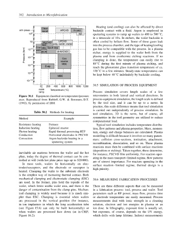
Figure 30.1 Equipment classified on temperature/pressure micrometres in both lateral and vertical directions. In
axes. Reproduced from Rubloff, G.W. & Boronaro, D.T. process-equipment simulation, the length scale is defined
(1992), by permission of IBM by the tool size, and it can be up to a metre. In
practice, this scale difference means that tool simulation
is carried out independently of process simulation. In
Table 30.2 Methods for heating
tool simulation, 3D is the norm, but of course, all
Method Example symmetries in the tool geometry are utilized to reduce
computational load.
Resistance heating Furnace Typical tool simulation includes temperature distribu-
Induction heating Epitaxial reactor tion, flow patterns and plasma properties. Mass, momen-
Photon heating Rapid thermal processing RTP tum, energy and charge balances are calculated. Plasma
Conduction Horizontal electrodes in PECVD modelling is difficult because it involves so many param-
Convection Argon backside heating in a
eters: collision cross-sections, ionization, attachment,
sputtering system
recombination, dissociation, and so on. These plasma
reactions must then be combined with surface reactions
(deposition or etching). Taken together, these determine,
inevitable air mattress between the wafer and the hot for instance, PECVD film uniformity. For reactors oper-
plate, today the degree of thermal contact can be con- ating in the mass transport–limited regime, flow patterns
trolled at will (with hot plate price tags up to $20 000). are of utmost importance. For reactors operating in the
In most tools, wafers lie horizontally on elec- surface reaction–limited regime, thermal design is a
trodes/susceptors, and the electrode or susceptor is high priority.
heated. Clamping the wafer to the substrate electrode
is the simplest way of increasing thermal contact. Both
mechanical clamping and electrostatic clamping (ESC) 30.6 MEASURING FABRICATION PROCESSES
are used. In the former, pins hold the topside of the
wafer, which limits usable wafer area, and there is the There are three different aspects that can be measured
danger of contamination from the clamp pins. Mechan- in a fabrication process: tool, process and wafer. Tool
ical clamping is widely used because it is much sim- parameters such as RF power, mass flow, process time
pler than ESC. Clamping is essential when wafers or electrode temperature are easily measured. Process
are processed in the vertical position (for instance, measurements deal with ionic strength in a cleaning
in ion implanters in which the long acceleration tube solution, electron and ion energies in plasma or an
(see Figure 15.6) can only be built horizontally) or ion dose. In lithography, exposure time is usually set,
when wafers are processed face down (as in CMP, but exposure, of course, depends on the UV energy,
Figure 16.2). which drifts with lamp lifetime. Indirect measurements