
Page 366 - Sami Franssila Introduction to Microfabrication
P. 366
Cleanrooms 345
taken into an airlock where the inner packing material 35.2 CLEANROOM SUBSYSTEMS
(which was wrapped in the cleanroom of wafer, target
35.2.1 Construction
or tool manufacturer) is removed. Depending on the
item, manual cleaning with isopropyl alcohol may
Cleanroom envelopes – walls, floor, ceiling, and so
be undertaken.
on – need to be made of materials compatible with the
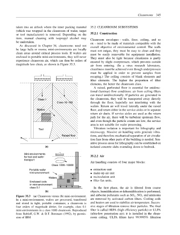
As discussed in Chapter 34, cleanrooms need not
overall objective of environmental control. The walls
be large halls or rooms; mini-environments are locally
must not outgas, they must be easy to clean and they
clean areas around critical process tools. If wafers are
must be easily removable for equipment installation.
enclosed in portable mini-environments, they will never
They must also be tight because cleanliness is partly
experience cleanroom air, which can then be orders of
ensured by slight overpressure, which prevents outside
magnitude less clean, as shown in Figure 35.3.
air from entering. (In a virus research laboratory,
cleanliness must be achieved even though underpressure
must be applied in order to prevent samples from
escaping.) The ceiling consists of blank elements and
filter elements. The higher the proportion of filter
elements, the better the cleanroom class.
A raised, perforated floor is essential for unidirec-
tional (laminar) flow conditions: air from ceiling filters
can travel unidirectionally. If particles are generated in
Class 1 the cleanroom, they will be transported away directly
Class 10−100 through the floor, hopefully not interfering with the
wafers. Return air will travel laterally under the raised
Wafers floor, and return either in the service aisles or in separate
return air ducts. If service aisles are used as the return
path for the air, there will be turbulent upstream flow,
and even though the particle counts are low, the service
area is not suitable for wafer processing.
Tool Vibration isolation is important for lithography and
microscopy. Massive air-handling units generate vibra-
Raised floor tions, and therefore mechanical separation of air circula-
tion fans from other parts of the building is needed. Sen-
sitive process areas for lithography can be established on
(a) isolated concrete slabs extending down to bedrock.
Mini-environments
for tool and wafer 35.2.2 Air
transport
Air handling consists of four major blocks:
Class 1000−10000
Portable wafer • extraction unit
mini-environment • make-up air unit
Wafers • recirculation unit
Enclosed tools • filter fan units.
in mini-environment
class 0.1 In the first phase, the air is filtered from coarse
(b) objects, humidification or dehumidification is performed,
and airborne pollutants such as SO x , NO x and ammonia
Figure 35.3 (a) Cleanroom versus (b) mini-environment.
In a mini-environment, wafers are processed, transferred are removed by activated carbon filters. Cooling coils
and stored in tight, portable containers; a cleanroom is and heaters are used to stabilize air temperature. Succes-
four orders of magnitude dirtier, for example, class 0.1 sive stages of filtration remove finer particles. The final
mini-environments in a class 1000 cleanroom. Reproduced filter is called HEPA (high efficiency particle) or ULPA
from Rubloff, G.W. & D.T. Boronaro (1992), by permis- (ultra-low penetration air); it is installed in the clean-
sion of IBM room ceiling. ULPA filters have 99.9995% filtration