
Page 138 - Lindens Handbook of Batteries
P. 138
BATTERY DESIGN 5.15
process is critical to the ultimate life and safety of the battery. The two (2) major considerations to
be addressed include:
1. Voltage and current control to prevent overcharge (overvoltage) and overdischarge (undervoltage).
These controls can be located in the battery pack for redundancy or be part of the device’s system
design, which includes the charger.
2. Temperature sensing and response to maintain the battery temperature within the range specified
by the battery manufacturers.
5.5.1 Charge Control
The controls for voltage and current during charge for most non-lithium rechargeable chemistry bat-
teries are contained in the charger. Nickel-cadmium and nickel-metal hydride batteries may be charged
over a fairly broad range of input current, ranging from less than a 0.05C rate to greater than 1.0C.
As the charge rate increases, the degree of charger control increases. While a simple, constant current
control circuit may be adequate for a battery being charged at a 0.05C rate, it would not suffice at a rate
of 0.5C or greater. Protective devices may be installed within the battery pack to stop the charge in the
event of an unacceptable temperature rise. The thermal devices that can be used include the following:
1. Thermistor. This device is a calibrated resistor whose value varies inversely with temperature. The
nominal resistance is its value at 25°C. The nominal value is in the Kohm range with 10K being
the most common. By proper placement within the battery pack, a measurement of the temperature
of the battery is available and T max , T min , and ∆T/∆t or other such parameters can be established
for charge control. In addition, the battery temperature can be sensed during discharge to control
the discharge, e.g., turn off loads to lower the battery temperature, in the event that excessively
high temperatures are reached during the discharge. Temperature measurement can also be used
to determine when a nickel battery is fully charged: the rate of change of temperature when a suf-
ficiently high charge current is used to charge the nickel pack will indicate completion. 5
2. Thermostat (temperature cutoff, TCO). This
device operates at a fixed temperature and is
used to cut off the charge (or discharge) when
a preestablished internal battery temperature
is reached. TCOs are usually resettable. They
are connected in series within the cell stack.
3. Thermal fuse. This device is wired in series
with the cell stack and will open the circuit
when a predetermined temperature is reached.
Thermal fuses are included as a protection
against thermal runaway and are normally
set to open at approximately 30–50°C above
the maximum battery operating temperature.
They do not reset.
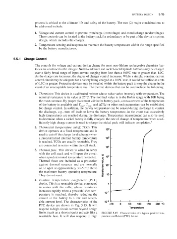
4. Positive temperature coefficient (PTC)
device. This is a resettable device, connected
in series with the cells, whose resistance
increases rapidly when a preestablished tem-
perature is reached, thereby reducing the
current in the battery to a low and accept-
able current level. The characteristics of the
PTC device are shown in Fig. 5.15. It will
respond to high circuit current beyond design
limits (such as a short circuit) and acts like a FIGURE 5.15 Characteristics of a typical positive tem-
resettable fuse. It will also respond to high perature coefficient (PTC) device.