
Page 139 - Lindens Handbook of Batteries
P. 139
5.16 PRINCIPLES OF OPERATION
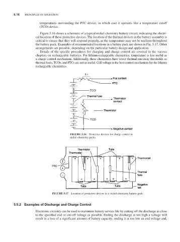
temperatures surrounding the PTC device, in which case it operates like a temperature cutoff
(TCO) device.
Figure 5.16 shows a schematic of a typical nickel-chemistry battery circuit, indicating the electri-
cal location of these protective devices. The location of the thermal devices in the battery assembly is
critical to ensure that they will respond properly, as the temperature may not be uniform throughout
the battery pack. Examples of recommended locations in a battery pack are shown in Fig. 5.17. Other
arrangements are possible, depending on the particular battery design and application.
Details of the specific procedures for charging and charge control are covered in the various
chapters on rechargeable batteries. For lithium-rechargeable chemistries, temperature is less useful as
a charge control mechanism. Additionally, these chemistries have lower thermal run-away thresholds so
thermal fuses, TCOs, and PTCs are not as useful. Cell voltage is the best control mechanism for the lithium
rechargeable chemistries.
FIGURE 5.16 Protective devices for charge control in
nickel-chemistry packs.
FIGURE 5.17 Location of protective devices in a nickel-chemistry battery pack.
5.5.2 Examples of Discharge and Charge Control
Electronic circuitry can be used to maximize battery service life by cutting off the discharge as close
to the specified end or cut-off voltage as possible. Ending the discharge at too high a voltage will
result in a loss of a significant amount of battery capacity; ending it at too low an end voltage and,