
Page 134 - Lindens Handbook of Batteries
P. 134
BATTERY DESIGN 5.11
The resistance may be significant, however, if the tab structure is used as a fuse for high-rate dis-
charge cells in larger arrays. Due to the need for high discharge currents, such as in power tools or
electric vehicles, normal cell protection devices such as PTCs may not be utilized. However, to protect
against a cell short or other potentially damaging cell failure, particularly in large parallel combinations
of cells, the tab interconnect can be constructed to be a fuse element. Fused links such as this can be
used to prevent adjacent parallel connected cells from delivering excessive current into a shorted cell.
Resistance spot welding is the welding method of choice. Care must be taken to ensure a proper
weld without burning through the cell container. Excessive welding temperatures could also result
in damage to the internal cell components and venting may occur. Typically AC or capacitance dis-
charge welders are used.
In all instances the weld should have a clean appearance, with discoloration of the base materials
kept to a minimum. At least two weld spots should be made at each connection joint. When the weld is
tested by pulling the two pieces apart, the weld must hold while the base metal tears. For tabs, the weld
diameter, as a rule of thumb, should be three to four times the tab thickness. For example, a 0.125-mm-
thick tab should have a tear diameter of 0.375–0.5 mm. Statistical techniques of weld pull strength for
process control are helpful, but a visual inspection of the weld diameter must accompany the inspection
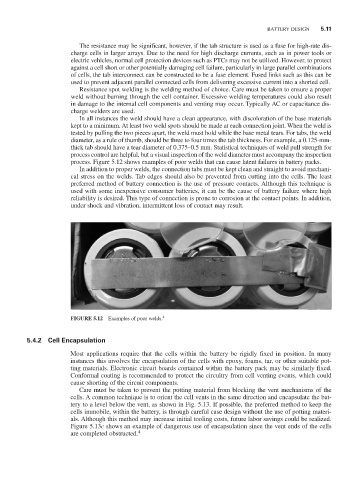
process. Figure 5.12 shows examples of poor welds that can cause latent failures in battery packs.
In addition to proper welds, the connection tabs must be kept clean and straight to avoid mechani-
cal stress on the welds. Tab edges should also be prevented from cutting into the cells. The least
preferred method of battery connection is the use of pressure contacts. Although this technique is
used with some inexpensive consumer batteries, it can be the cause of battery failure where high
reliability is desired. This type of connection is prone to corrosion at the contact points. In addition,
under shock and vibration, intermittent loss of contact may result.
FIGURE 5.12 Examples of poor welds.
4
5.4.2 Cell Encapsulation
Most applications require that the cells within the battery be rigidly fixed in position. In many
instances this involves the encapsulation of the cells with epoxy, foams, tar, or other suitable pot-
ting materials. Electronic circuit boards contained within the battery pack may be similarly fixed.
Conformal coating is recommended to protect the circuitry from cell venting events, which could
cause shorting of the circuit components.
Care must be taken to prevent the potting material from blocking the vent mechanisms of the
cells. A common technique is to orient the cell vents in the same direction and encapsulate the bat-
tery to a level below the vent, as shown in Fig. 5.13. If possible, the preferred method to keep the
cells immobile, within the battery, is through careful case design without the use of potting materi-
als. Although this method may increase initial tooling costs, future labor savings could be realized.
Figure 5.13c shows an example of dangerous use of encapsulation since the vent ends of the cells
are completed obstructed. 4