
Page 287 - Lindens Handbook of Batteries
P. 287
MERCURIC OXIDE BATTERIES 12.7
Outer top
Inner top
Grommet
Adaptor tube Anodes
Absorbent Barrier
Outer top
Cathodes
Inner top
Inner can Wound anode
Outer can
Barrier
Inner can
Adaptor tube
Vent Cathode
Insulating slug Vent
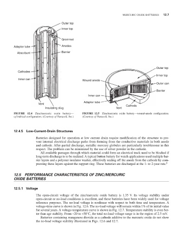
FIGURE 12.4 Zinc/mercuric oxide battery— FIGURE 12.5 Zinc/mercuric oxide battery—wound-anode configuration.
cylindrical configuration. (Courtesy of Duracell, Inc.) (Courtesy of Duracell, Inc.)
12.4.5 Low-Current-Drain Structures
Batteries designed for operation at low current drain require modification of the structure to pre-
vent internal electrical discharge paths from forming from the conductive materials in both anode
and cathode. After partial discharge, metallic mercury globules are particularly troublesome in this
respect. The problem can be minimized by the use of silver powder in the cathode.
All available passages through which material could form an electrical track need to be blocked if
long-term discharge is to be realized. A typical button battery for watch applications used multiple bar-
rier layers and a polymer insulator washer, effectively sealing off the anode from the cathode by com-
pressing these layers against the support ring. These batteries are discharged at the 1- to 2-year rate. 8
12.5 PERFORmANCE CHARACTERISTICS OF ZINC/mERCuRIC
OXIDE BATTERIES
12.5.1 Voltage
The open-circuit voltage of the zinc/mercuric oxide battery is 1.35 V. Its voltage stability under
open-circuit or no-load conditions is excellent, and these batteries have been widely used for voltage
reference purposes. The no-load voltage is nonlinear with respect to both time and temperature. A
voltage-time curve is shown in Fig. 12.6. The no-load voltage will remain within 1% of its initial value
for several years. A voltage-temperature curve is shown in Fig. 12.7. Temperature stability is even bet-
ter than age stability. From -20 to +50°C, the total no-load voltage range is in the region of 2.5 mV.
Batteries containing manganese dioxide as a cathode additive to the mercuric oxide do not show
the no-load voltage stability illustrated in Figs. 12.6 and 12.7.