
Page 315 - Lindens Handbook of Batteries
P. 315
BUTTOn CELL BATTErIES: SILVEr OxIDE–ZInC AnD ZInC-AIr SYSTEmS 13.21
Dry conditions in the anode promote early cementation of the partially discharged anode, and there
is usually an increase in the battery’s internal impedance.
There are four main electrical measurements for zinc/air cells:
• Open-circuit voltage
• Closed-circuit or operating voltage
• Internal cell impedance
• Limiting current
The first and second are easily measured. Open-circuit voltage represents the potential for current
to flow and is usually 1.4 to 1.5 V for commercial zinc/air cells. Closed-circuit is the actual voltage
that the cell can support when a defined load has been applied that is demanding a current to flow
through a test circuit or through an actual device under test. The power being delivered is the product
of voltage times amps, which is generally in the range of a few milliwatts for a zinc/air button cell.
The internal impedance of the battery is usually measured with an LCr meter and accounts for
the AC components of resistance, capacitance, and inductance. For fresh zinc/air button cells, the
impedance rises as one goes to low frequency levels. The impedance drops as cells are discharged and
remains low until the end of discharge as the last of the available zinc is converted to zinc oxide.
The most dynamic and perhaps interesting electrical property of the zinc/air system is the limit-
ing current, so named because it occurs when an increasing external load is applied, the cell has
reached a point where there is no corresponding increase in current, and the voltage of the cell drops
precipitously. Below the limiting current value, the cell is not internally rate limited; it is the external
circuit that is limiting the flow of electrons. At the limiting current, there is a rate limiting process
that has been maximized. At the beginning of discharge, the rate limiting process of the fresh cell
is usually oxygen diffusion within the cathode, PTFE diffusion rate, or the vent hole configuration
of the can. As discharge continues, the anode active electrode area (metallic zinc surface) decreases
and becomes the rate limiting process.
13.9 PERFORMANCE CHARACTERISTICS
13.9.1 Cell sizes
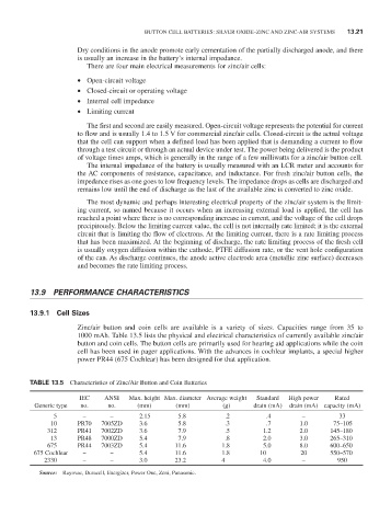
Zinc/air button and coin cells are available is a variety of sizes. Capacities range from 35 to
1000 mAh. Table 13.5 lists the physical and electrical characteristics of currently available zinc/air
button and coin cells. The button cells are primarily used for hearing aid applications while the coin
cell has been used in pager applications. With the advances in cochlear implants, a special higher
power Pr44 (675 Cochlear) has been designed for that application.
taBle 13.5 Characteristics of Zinc/Air Button and Coin Batteries
IEC AnSI max. height max. diameter Average weight Standard High power rated
Generic type no. no. (mm) (mm) (g) drain (mA) drain (mA) capacity (mA)
5 – – 2.15 5.8 .2 .4 – 33
10 Pr70 7005ZD 3.6 5.8 .3 .7 1.0 75–105
312 Pr41 7002ZD 3.6 7.9 .5 1.2 2.0 145–180
13 Pr48 7000ZD 5.4 7.9 .8 2.0 3.0 265–310
675 Pr44 7003ZD 5.4 11.6 1.8 5.0 8.0 600–650
675 Cochlear – – 5.4 11.6 1.8 10 20 550–570
2330 – – 3.0 23.2 4 4.0 – 950
Source: rayovac, Duracell, Energizer, Power One, Zeni, Panasonic.