
Page 318 - Lindens Handbook of Batteries
P. 318
13.24 PrImArY BATTErIES
1.5
1.4
1.3
Voltage 1.2
1.1
1.0
0.9
0 50 100 150 200 250 300 350
mAh
2 mA 5 mA 8 mA 10 mA 12 mA 14 mA
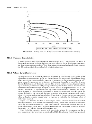
FiGURE 13.21 Discharge curves for a Pr48 (13) zinc/air battery at six different rates of discharge
13.9.5 discharge Characteristics
A set of discharge curves, typical of zinc/air button batteries at 20°C, is presented in Fig. 13.21. At
low to moderate current levels, the discharge curves are relatively flat. As the discharge current goes
up, the discharge voltage goes down. When the discharge rate approaches the cell’s limiting current,
the delivered capacity is decreased and cell polarization increases.
13.9.6 voltage-Current Performance
The catalytic activity of the cathode, along with the amount of oxygen access to the cathode, gener-
ally defines the voltage-current profile of a zinc/air battery. Oxygen access is defined by the degree
of air access to the battery’s cathode. Improved oxygen access to the cathode increases the cell’s
power output. Oxygen access can be improved by increasing the number or size of the air access
holes in the battery case. If the number and size of the air holes are kept constant, the power capabil-
ity of the battery can be increased by raising the limiting current of the cathode. To minimize the
detrimental effects of water vapor transport, air access needs to be properly balanced. 36,37 In a low
humidity environment, a high rate of water vapor loss accelerates dry-out, lowering the battery’s
overall capacity. In a high humidity environment, a high rate of water vapor gain takes up the free
volume designed for the zinc anode discharge expansion, reducing the battery’s overall capacity
along with causing possible swelling or leakage. Understanding the maximum current requirements
of the application using the zinc/air battery is important to minimizing the detrimental effects of
water vapor transport.
Figure 13.22 illustrates the effect of increasing the total air hole circumference on the cathode
limiting current for a Pr48 (size 13) zinc/air battery. Limiting current is the maximum current a zinc/
air battery or cathode can deliver for a given set of conditions. The limiting current is measured by
potentiostatically setting the battery or cathode to a voltage of 0.9 V and then measuring the current
output after 1 to 5 minutes from the initiation of the test.
Since the limiting current is a measure of air access to the cathode, this measurement can also be
used to determine water vapor transport rates (see Fig. 13.23). Since internal electrolyte evaporation is