
Page 353 - Lindens Handbook of Batteries
P. 353
14.18 PriMAry BATTerieS
cathode by precipitation of the discharge product (cathode limited). Current designs are typi-
cally limited by the cathode so that some lithium remains at the end of discharge. The good
shelf life of the Li/SO cell results from the protective lithium dithionite film on the anode
2
formed by the initial reaction of lithium and SO . it prevents further reaction and loss of
2
capacity during storage.
Most Li/SO cells are now fabricated in a balanced construction where the lithium:sulfur
2
dioxide stoichiometric ratio is in the range of Li:SO = 0.9 – 1.05:1. With the earlier designs,
2
where the ratio was on the order of Li:SO = 1.5:1, high temperatures, cell venting, or rup-
2
ture and fires due to an exothermic reaction between residual lithium and acetonitrile, in the
absence of SO , could occur on deep or forced discharge. Lithium cyanide, methane and other
2
organic products can also be generated through this reaction. in the balanced cell, the anode is
protected by residual SO and remains passivated. The conditions for the hazardous reaction
2
16
are minimized since some protective SO remains in the electrolyte. A higher negative cell
2
voltage, in reversal, of the balanced cell is also beneficial when using diode protection, which
is used in some designs to bypass the current through the cell and minimize the adverse effects
of reversal.
The use of a current collector, typically an inlayed stripe of copper metal, also helps to
maintain the integrity of the anode and leads to formation of a short-circuit mechanism since
copper dissolution on cell reversal causes plated copper on the cathode to form an internal ohmic
bridge.
14.5.2 Construction
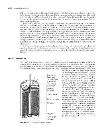
The Li/SO cell is typically fabricated in a cylindrical structure, as shown in Fig. 14.8. A jelly-roll
2
construction is used, made by spirally winding rectangular strips of lithium foil, a microporous
polypropylene separator, the cathode electrode (a Teflon-acetylene black mix pressed on an expand-
ed aluminum screen), and a second separator layer. This design provides the high surface area and
low cell resistance to obtain high-current
and low-temperature performance. The roll
Terminal tab is inserted in a nickel-plated steel can, with
Epoxy clear the positive cathode tab welded to the pin
Hermetic glass of a glass-to-metal seal and the anode tab
to metal seal welded to the cell case, the top is welded
Hermetically in place, and the electrolyte/depolarizer is
added. The safety vent releases when the
sealed can internal cell pressure reaches excessive lev-
Insulator els, typically 2.41 MPa (350 psi) caused by
Separator inadvertent abusive use, such as overheat-
ing or short-circuiting, and prevents cell
Lithium anode rupture or explosion. The vent activates at
approximately 95°C, well above the upper
Carbon cathode temperature limit for operation and storage,
safely relieving the excess pressure and
Cell case preventing possible cell rupture. Additional
construction details have been previously
16
described. it is important to employ a
corrosion-resistant glass to prevent lithia-
tion of the glass due to the potential differ-
Insulator ence between the cell case and the pin of
the glass-to-metal seal.
Rupture vent
Fill eyelet
FIGURE 14.8 Lithium/sulfur dioxide batteries.