
Page 373 - Lindens Handbook of Batteries
P. 373
14.38 PriMAry BATTerieS
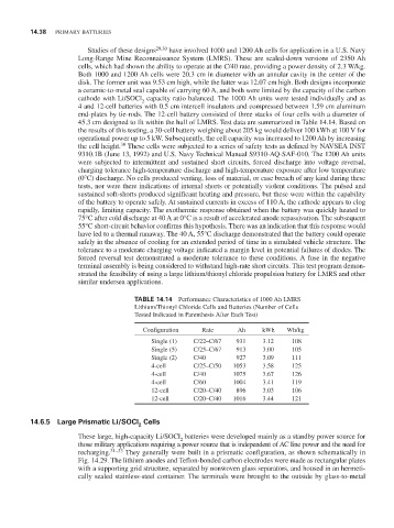
Studies of these designs 29,30 have involved 1000 and 1200 Ah cells for application in a U.S. Navy
Long-range Mine reconnaissance System (LMrS). These are scaled-down versions of 2350 Ah
cells, which had shown the ability to operate at the C/40 rate, providing a power density of 2.3 W/kg.
Both 1000 and 1200 Ah cells were 20.3 cm in diameter with an annular cavity in the center of the
disk. The former unit was 9.53 cm high, while the latter was 12.07 cm high. Both designs incorporate
a ceramic-to-metal seal capable of carrying 60 A, and both were limited by the capacity of the carbon
cathode with Li/SOCl capacity ratio balanced. The 1000 Ah units were tested individually and as
2
4 and 12-cell batteries with 0.5 cm intercell insulators and compressed between 1.59 cm aluminum
end-plates by tie-rods. The 12-cell battery consisted of three stacks of four cells with a diameter of
45.3 cm designed to fit within the hull of LMrS. Test data are summarized in Table 14.14. Based on
the results of this testing, a 30-cell battery weighing about 205 kg would deliver 100 kWh at 100 V for
operational power up to 5 kW. Subsequently, the cell capacity was increased to 1200 Ah by increasing
30
the cell height. These cells were subjected to a series of safety tests as defined by NAVSeA iNST
9310.1B (June 13, 1992) and U.S. Navy Technical Manual S9310-AQ-SAF-010. The 1200 Ah units
were subjected to intermittent and sustained short circuits, forced discharge into voltage reversal,
charging tolerance high-temperature discharge and high-temperature exposure after low temperature
(0°C) discharge. No cells produced venting, loss of material, or case breach of any kind during these
tests, nor were there indications of internal shorts or potentially violent conditions. The pulsed and
sustained soft-shorts produced significant heating and pressure, but these were within the capability
of the battery to operate safely. At sustained currents in excess of 110 A, the cathode appears to clog
rapidly, limiting capacity. The exothermic response obtained when the battery was quickly heated to
75°C after cold discharge at 40 A at 0°C is a result of accelerated anode repassivation. The subsequent
55°C short-circuit behavior confirms this hypothesis. There was an indication that this response would
have led to a thermal runaway. The 40 A, 55°C discharge demonstrated that the battery could operate
safely in the absence of cooling for an extended period of time in a simulated vehicle structure. The
tolerance to a moderate charging voltage indicated a margin level in potential failures of diodes. The
forced reversal test demonstrated a moderate tolerance to these conditions. A fuse in the negative
terminal assembly is being considered to withstand high-rate short circuits. This test program demon-
strated the feasibility of using a large lithium/thionyl chloride propulsion battery for LMrS and other
similar undersea applications.
TABLE 14.14 Performance Characteristics of 1000 Ah LMrS
Lithium/Thionyl Chloride Cells and Batteries (Number of Cells
Tested indicated in Parenthesis After each Test)
Configuration rate Ah kWh Wh/kg
Single (1) C/22–C/67 931 3.12 108
Single (5) C/25–C/67 913 3.00 105
Single (2) C/40 927 3.09 111
4-cell C/25–C/50 1053 3.58 125
4-cell C/40 1075 3.67 126
4-cell C/60 1004 3.41 119
12-cell C/20–C/40 896 3.03 106
12-cell C/20–C/40 1016 3.44 121
14.6.5 Large Prismatic Li/SOCl Cells
2
These large, high-capacity Li/SOCl batteries were developed mainly as a standby power source for
2
those military applications requiring a power source that is independent of AC line power and the need for
recharging. 31–33 They generally were built in a prismatic configuration, as shown schematically in
Fig. 14.29. The lithium anodes and Teflon-bonded carbon electrodes were made as rectangular plates
with a supporting grid structure, separated by nonwoven glass separators, and housed in an hermeti-
cally sealed stainless-steel container. The terminals were brought to the outside by glass-to-metal