
Page 173 - Low Temperature Energy Systems with Applications of Renewable Energy
P. 173
Heat pumps in the drying industry 163
area was WESTAIR, which has been manufacturing such equipment for over 10 years.
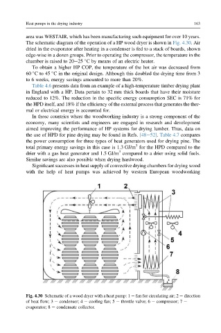
The schematic diagram of the operation of a HP wood dryer is shown in Fig. 4.30. Air
dried in the evaporator after heating in a condenser is fed to a stack of boards, shown
edge-wise in a dozen groups. Prior to operating the compressor, the temperature in the
chamber is raised to 20e25 C by means of an electric heater.
To obtain a higher HP COP, the temperature of the hot air was decreased from
60 Cto45 C in the original design. Although this doubled the drying time from 3
to 6 weeks, energy savings amounted to more than 20%.
Table 4.6 presents data from an example of a high-temperature timber drying plant
in England with a HP. Data pertain to 32 mm thick boards that have their moisture
reduced to 12%. The reduction in the specific energy consumption SEC is 71% for
the HPD itself, and 18% if the efficiency of the external process that generates the ther-
mal or electrical energy is accounted for.
In those countries where the woodworking industry is a strong component of the
economy, many scientists and engineers are engaged in research and development
aimed improving the performance of HP systems for drying lumber. Thus, data on
the use of HPD for pine drying may be found in Refs. [48e52]. Table 4.7 compares
the power consumption for three types of heat generators used for drying pine. The
3
total primary energy savings in this case is 1.3 GJ/m for the HPD compared to the
3
drier with a gas heat generator and 1.5 GJ/m compared to a drier using solid fuels.
Similar savings are also possible when drying hardwood.
Significant successes in heat supply of convective drying chambers for drying wood
with the help of heat pumps was achieved by western European woodworking
Fig. 4.30 Schematic of a wood dryer with a heat pump: 1 e fan for circulating air; 2 e direction
of heat flow; 3 e condenser; 4 e cooling fan; 5 e throttle valve; 6 e compressor; 7 e
evaporator; 8 e condensate collector.