
Page 170 - Low Temperature Energy Systems with Applications of Renewable Energy
P. 170
160 Low-Temperature Energy Systems with Applications of Renewable Energy
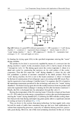
Fig. 4.28 Scheme of a grain HPD with heat regeneration: 1 e HP evaporator; 2 e“cold” drying
chamber; 3 e condenser; 4 e regenerative heat exchanger; 5 e electric heater of a DA; 6 e
“warm” drying chamber; 7 e fan; 8 e HP compressor; 9 e throttle; 10 e regenerative heat
exchanger; 11, 12 event and supply air valves.
for heating the drying agent (DA) to the specified temperature entering the “warm”
drying chamber.
The product to be dried is successively supplied by means of a conveyor into the
drying chambers 2 and 6. In the circulation circuit a DA is fed by means of the fan
7 through the valve 12. The drying agent enters the cooler-evaporator 1, where it is
dried and cooled by condensing the moisture on the cold surface of the cooler-
evaporator. Then the DA enters the “cold” drying chamber 2, where the dry cold
DA assimilates a portion of moisture contained in the dried product. From the
“cold” drying chamber, the DA is sent to the heater-condenser 3, where it is heated
by the heat of condensation of hot refrigerant vapors circulating in the HP circuit. Pass-
ing the regenerative heat exchanger 4 and the heater 5 in sequence, the DA is heated to
the maximum temperature permitted by the technology and enters the “warm” drying
chamber 6. The heated drying agent absorbs the residual moisture from the product and
enters the regenerative heat exchanger 4, heating the DA after the heater-condenser 3.
Finally, the DA is discharged into the atmosphere through the valve 11.
Raising the temperature of the DA entering heater 5 from the exhaust air heat leads
to a 25e30% reduction in the energy consumption to achieve the specified temperature
entering the “warm” drying chamber [67]. Combining the HPD with the cooling cham-
bers that provide final drying and improving grain quality allows a significant amount
of cooling air heat to be utilized (Fig. 4.29).
Thus, as shown in this section, heat pump technology for heat supply took a step
beyond the needs of public heat consumers long ago and now finds applications in
various heat engineering processes, especially in industrial drying processes, particu-
larly grain drying. However, one of the most promising directions for the use of heat