
Page 19 - Low Temperature Energy Systems with Applications of Renewable Energy
P. 19
8 Low-Temperature Energy Systems with Applications of Renewable Energy
Expansion valve: An expansion valve is used to suddenly drop the high pressure created by a
compressor, and in so doing reduce the cooling agent temperature to a level lower than the
heat source, thus renewing the cycle. This throttling process is the simplest one to achieve the
cooling via the Joule-Thomson effect mentioned earlier.
1.4.3 Historical facts on heat pumps
Now that we understand the basic principles of heat pumps/refrigerators, it is inter-
esting to look back at how these now common devices came into being.
The principle of the heat pump follows from the work of Carnot and the description
of the Carnot cycle, published in his book “Reflections on the Motive Power of Fire
and on Machines Fitted to Develop that Power” in 1824. The practical heat pump sys-
tem was introduced by William Thomson in 1852. It was called the Heat Multiplier
and showed how to use a refrigerator efficiently for heating purposes. In substantiating
his suggestion, Thomson pointed out that the limited energy resources would not allow
the burning of fuel in heating furnaces forever, and that his heat multiplier would
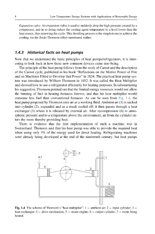
consume less fuel than conventional furnaces. As can be seen from Fig. 1.4, the
heat pump proposed by Thomson uses air as a working fluid. Ambient air (1) is sucked
into cylinder (2), expanded and as a result cooled off; it then passes through a heat
exchanger (3) where it is reheated by external air. After recompression (6) to atmo-
spheric pressure and to a temperature above the environment, air from the cylinder en-
ters the room thereby providing heat.
There is evidence that the first implementation of such a machine was in
Switzerland. Thomson said that his heat pump was able to provide the required heat
when using only 3% of the energy used for direct heating. Refrigerating machines
were already being developed at the end of the nineteenth century, but heat pumps
5
7 1
4
6
2
3
Fig. 1.4 The scheme of Thomson’s “heat multiplier”:1 ¼ ambient air; 2 ¼ input cylinder; 3 ¼
heat exchanger; 4 ¼ drive mechanism; 5 ¼ steam engine; 6 ¼ output cylinder; 7 ¼ room being
heated.