
Page 24 - Low Temperature Energy Systems with Applications of Renewable Energy
P. 24
Principles and operation of refrigeration and heat pump systems 13
lower temperature plus the work input to the cycle. This fact is always true whether the
cycles are ideal or real (by conservation of energy), and results in high coefficients of
performance for heat pumps.
1.5.2 Thermodynamic efficiency of vapor compression heat
pumps
The ideal heat pump derives its high performance from the isothermal heat transfer that
occurs at both the high- and low-temperature ends of the cycle. Practical consider-
ations and the natural saturation pressure-temperature relations for real fluids conspire
against such ideal heat transfer. Real heat pumps typically employ vapor compression
processes to achieve high temperatures needed for the application at hand. This results
in non-isothermal heat transfer between the heat pump working fluid and the space to
be heated. Isothermal heat transfer is still possible at the low-temperature end.
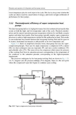
Figure 1.11 shows in simplified schematic form a heat pump that uses the vapor-
compression principle. There are five main components: a compressor (CP), a motor
(M), two heat exchangers (one an evaporator, EV, and one a cooler-condenser, CN)
and a throttle valve (TV). The motor drives the compressor which raises the pressure
of the working fluid from its saturation pressure corresponding to the temperature of
the condenser to the saturation pressure corresponding to the high-temperature
requirement.
The processes undergone by the heat pump working fluid are shown in Fig. 1.12:
(A) T-s diagram and (B) pressure-enthalpy (P-h) diagram. State d is the dew-point
where the compressed vapor first begins to condense upon cooling.
3
CN
4
CP M
TV
2
1
EV
Fig. 1.11 Vapor-compression heat pump schematic.